Mask and photoetching machine

A technology of reticle and lithography machine, which is applied to the photo-engraving process of photomechanical processing of originals, optics, and pattern surfaces, etc., can solve the problems of ghosting, light leakage at the edge of the lens, etc., and achieve the effect of solving ghosting.

Pending Publication Date: 2022-04-12
SHANGHAI HUALI MICROELECTRONICS CORP
View PDF0 Cites 0 Cited by
  • Summary
  • Abstract
  • Description
  • Claims
  • Application Information

AI Technical Summary

Problems solved by technology

[0005] The object of the present invention is to provide a mask plate and a photolithography machine to solve the problem of ghosting caused by light leakage at the edge of the lens of the photolithography machine in the existing photolithography process

Method used


Image

  • Mask and photoetching machine
  • Mask and photoetching machine
  • Mask and photoetching machine

Examples


Embodiment Construction

[0024] The reticle and photolithography machine proposed by the present invention will be further described in detail below with reference to the accompanying drawings and specific embodiments. Advantages and features of the present invention will be apparent from the following description and claims. It should be noted that all the drawings are in a very simplified form and use imprecise scales, and are only used to facilitate and clearly assist the purpose of illustrating the embodiments of the present invention.

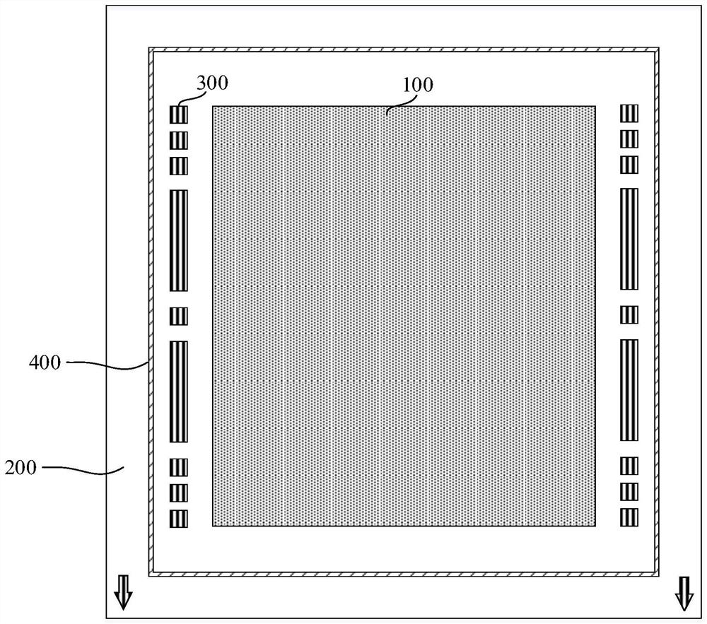
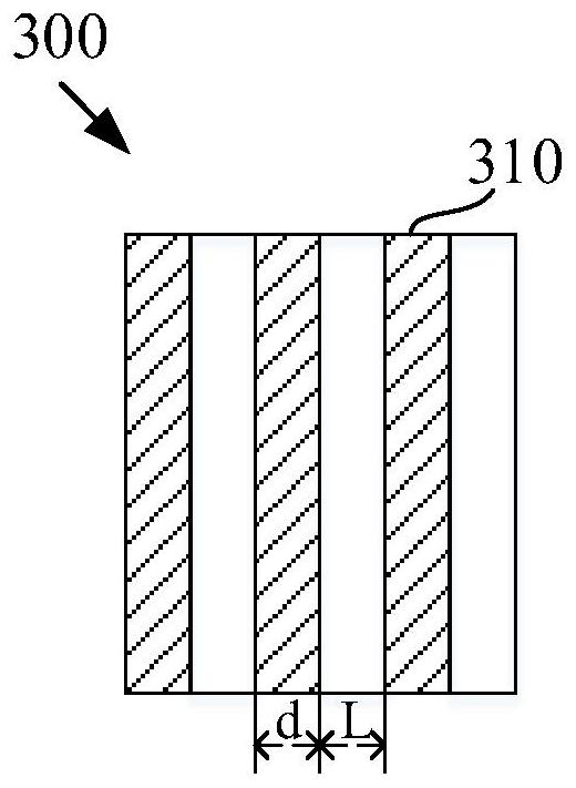
[0025] figure 2 A schematic diagram of a reticle provided by an embodiment of the present invention. Such as figure 2 As shown, the reticle provided in this embodiment includes an exposed area 100 and a non-exposed area 200 surrounding the exposed area 100 , and a plurality of auxiliary patterns 300 are disposed in the non-exposed area 200 .

[0026] Specifically, the pattern required for design is distributed in the exposure area 100, and after exposure, it ...


PUM


Abstract

The invention provides a mask plate and a photoetching machine. The mask plate comprises an exposure area and a non-exposure area surrounding the exposure area, a plurality of auxiliary patterns are arranged in the non-exposure area, each auxiliary pattern comprises a plurality of stripe patterns arranged at intervals, and the line width of each stripe pattern is smaller than the resolution limit of a photoetching machine. When a photoetching machine is used for exposing the mask plate, even if stray light can pass through a non-exposure area of the mask plate, the stripe pattern in the auxiliary pattern is difficult to identify because the stripe pattern does not reach the resolution of the photoetching machine, so that the auxiliary pattern cannot be mapped on a wafer; therefore, the ghosting problem caused by light leakage of the photoetching machine is effectively solved.

Description

technical field [0001] The invention relates to the field of semiconductor manufacturing, in particular to a mask plate and a photolithography machine. Background technique [0002] In the existing photolithography process, a step-scanning photolithography machine is mainly used for wafer exposure, which can reduce the image on the mask by 4 to 5 times and project it onto the wafer surface. And, when using a step-scanning photolithography machine for exposure, a small part of the wafer can be exposed each time, and after one pattern is exposed, continue to align and expose the next exposure position of the wafer. [0003] In a step-scan lithography machine, it mainly includes a light source, a converging lens, a reticle and a projection lens. During exposure, the light passes through the converging lens and the reticle in sequence, and then focuses on the surface of the wafer through the projection lens, thereby transferring the pattern in the exposure area of ​​the reticle...

Claims


Application Information

Patent Timeline
Patent Type & Authority Applications(China)
IPC IPC(8): G03F1/38
Inventor 胡健徐阳周世均王晓龙郑海昌陈力钧
Owner SHANGHAI HUALI MICROELECTRONICS CORP
Why Eureka
Try Eureka