near-eye display device

A near-eye display and display technology, applied in optical components, instruments, optics, etc., can solve the problem of ghosting on the display screen, and achieve the effect of solving ghosting and good display quality

Active Publication Date: 2021-06-22
CORETRONIC
View PDF0 Cites 0 Cited by
  • Summary
  • Abstract
  • Description
  • Claims
  • Application Information

AI Technical Summary

Problems solved by technology

However, when users use traditional near-eye displays, they often encounter ghost images on the display screen.

Method used


Image

  • near-eye display device
  • near-eye display device
  • near-eye display device

Examples


Embodiment Construction

[0024] The aforementioned and other technical content, features and effects of the present invention will be clearly presented in the following detailed description of a preferred embodiment with reference to the accompanying drawings. The directional terms mentioned in the following embodiments, such as: up, down, left, right, front or back, etc., are only referring to the directions of the drawings. Accordingly, the directional terms are used to illustrate and not to limit the invention.

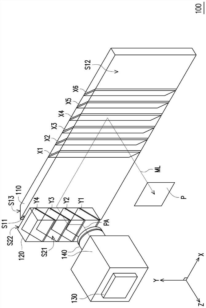
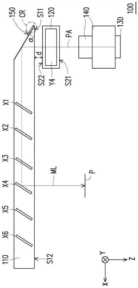
[0025] figure 1 A three-dimensional schematic diagram of a near-eye display device according to an embodiment of the present invention is shown. figure 2 draw figure 1 A side-view schematic of a near-eye display device. Please refer to figure 1 and figure 2 , the near-eye display device 100 of this embodiment includes a first waveguide element 110 , a second waveguide element 120 , a display 130 and a lens module 140 . The display 130 is used to provide the image beam ML. The seco...


PUM

PropertyMeasurementUnit
reflectanceaaaaaaaaaa

Abstract

A near-eye display device includes a display and a first waveguide element, and the first waveguide element includes a light incident surface, a light output surface, a reflective inclined surface and a plurality of light splitting elements. The image beam provided by the display enters the first waveguide element through the light-incident surface, is reflected by the reflective inclined surface in the first waveguide element, and passes to the light-splitting elements. These light-splitting elements split the image beam and leave the first waveguide element through the light-emitting surface. The reflective inclined surface has a first reflectivity distribution within the first incident angle range, and has a second reflectivity distribution within the second incident angle range. Angles in the second incident angle range are higher than angles in the first incident angle range, and an average reflectance of the first reflectance distribution is greater than an average reflectance of the second reflectance distribution. The near-eye display device of the present invention can effectively solve the ghost image problem caused by secondary reflection stray light, and provide good display quality.

Description

technical field [0001] The present invention relates to a head-mounted display device, and in particular to a near-eye display device. Background technique [0002] The near eye display (Near Eye Display, NED) can be applied to the display system of the head-mounted display (Head-mounted Display, HMD), and it is a next-generation killer product with great development potential. In terms of related applications of near-eye display technology, it can be divided into augmented reality (Augmented Reality, AR) technology and virtual reality (Virtual Reality, VR) technology. For augmented reality technology, relevant developers are currently working on how to provide the best image quality on the premise of the weight and thinness of the near-eye display. [0003] In an optical architecture for realizing augmented reality by using a near-eye display, the image beam used for display is emitted by a projection device, reflected by a semi-reflective and semi-transmissive optical ele...

Claims


Application Information

Patent Timeline
Patent Type & Authority Patents(China)
IPC IPC(8): G02B27/01
CPCG02B27/0172
Inventor 施智维魏仲廷郑权得
Owner CORETRONIC
Why Eureka
Try Eureka