Adjusting method and structure of liquid crystal display module of 5G range finder
A technology of a liquid crystal display module and an adjustment method, which is applied in the field of rangefinders, can solve problems such as difficulty in seeing the display content of the display screen, and achieve the effect of reducing reflection
- Summary
- Abstract
- Description
- Claims
- Application Information
AI Technical Summary
Problems solved by technology
Method used
Image
Examples
Embodiment 1
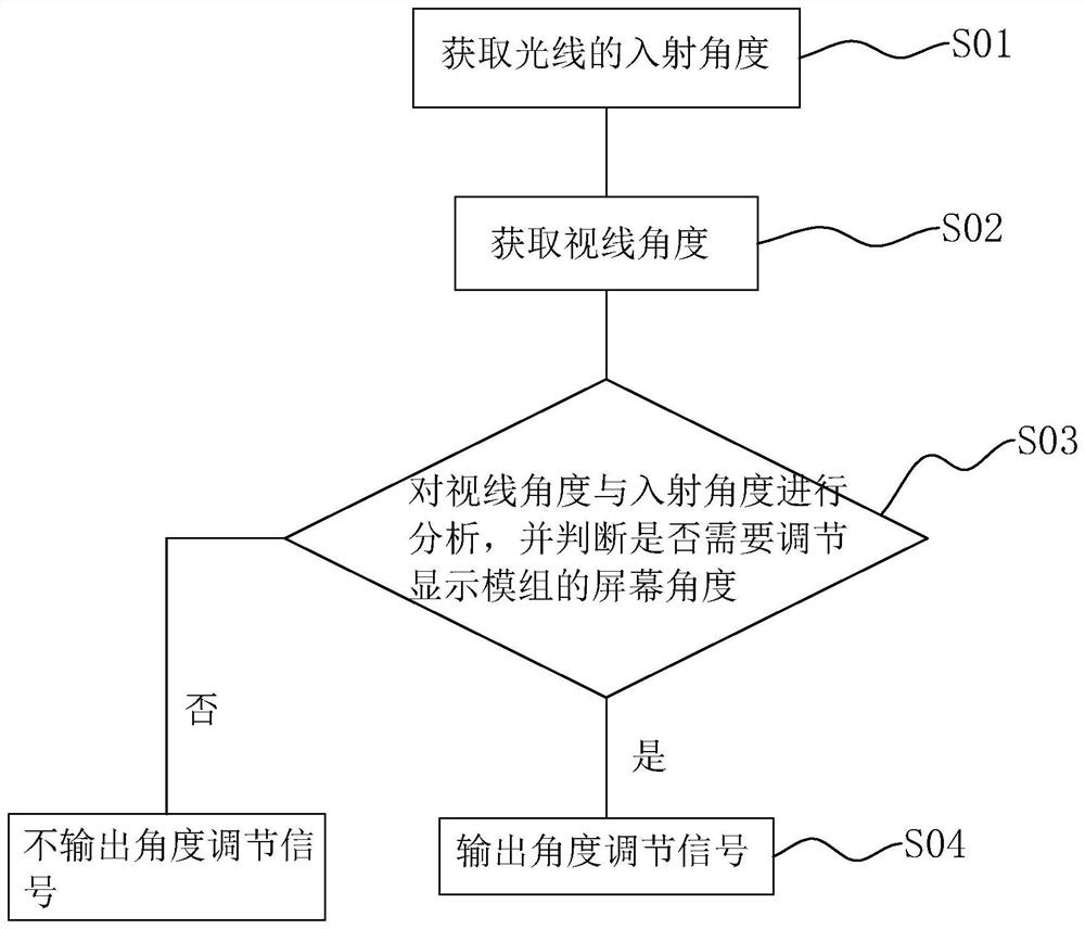
[0050] refer to figure 1 , the embodiment of the present application discloses an adjustment method of a liquid crystal display module of a 5G range finder, which is applied to a controller, wherein the adjustment method includes the following steps:
[0051] S01: Obtain the incident angle of light.
[0052] Specifically, the incident angle of light is the incident angle of outdoor sunlight. For example, a photoelectric angle sensor is installed on the housing 1 to detect the incident angle of light and send the detected data to the controller.
[0053] S02: Obtain the line of sight angle.
[0054] Specifically, the line-of-sight angle is the angle at which the user views the display screen during detection.
[0055] S03: Analyze the line-of-sight angle and incident angle, and judge whether it is necessary to adjust the screen angle of the display module 3 .
[0056] Specifically, the outgoing angle of the light can be obtained according to the incident angle of the light, ...
Embodiment 2
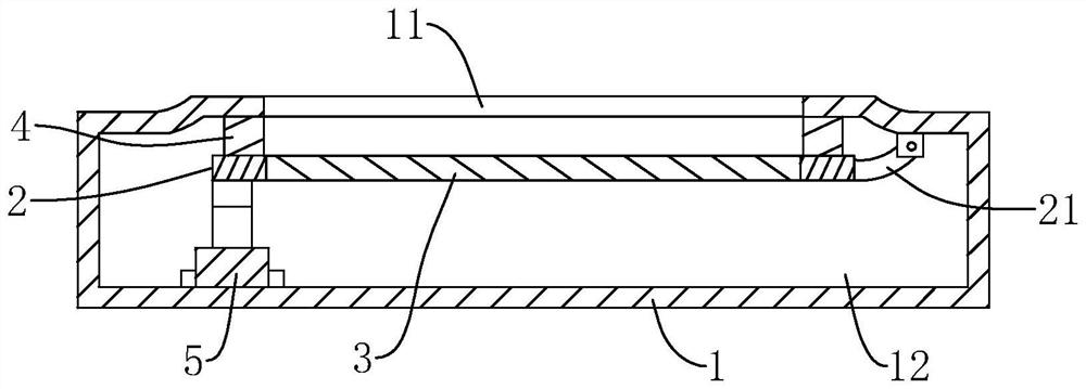
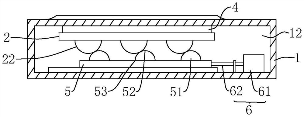
[0083] refer to figure 2 and image 3 , the embodiment of the present application discloses an adjustment structure of a liquid crystal display module of a 5G range finder, which is suitable for the adjustment method of the liquid crystal display module of a 5G range finder, wherein the adjustment structure includes a housing 1 and an installation frame 2 , the display module 3 and the controller, wherein the housing 1 is provided with an observation window 11, the inner wall of the housing 1 is provided with a cavity 12, the observation window 11 communicates with the cavity 12, and the installation frame 2 and the display module 3 are located Inside the cavity 12.
[0084] An elastic seal 4 is disposed on the side of the casing 1 facing the display module 3 , and the elastic seal 4 surrounds the observation window 11 . In this embodiment, the elastic sealing member 4 adopts a rubber ring, and the rubber ring is bonded and fixed to the housing 1 .
[0085] The display mod...
Embodiment 3
[0092] refer to Figure 4 The difference between this embodiment and Embodiment 2 is that the adjustment assembly includes a cam 7 and a driving member 6, the cam 7 is located on the side of the mounting frame 2 away from the connecting piece 21, the cam 7 is rotationally connected with the housing 1 through a rotating shaft 8, The side of the cam 7 is in contact with the mounting frame 2 . The cam 7 has a farthest point 71 and a closest point 72. The farthest point 71 is the farthest point on the side of the cam 7 from the rotating shaft 8, and the closest point 72 is the closest point on the side of the cam 7 to the rotating shaft 8. Normally, the screen angle of the display module 3 is 0°. At this time, the contact point between the cam 7 and the installation frame 2 is between the farthest point 71 and the closest point 72 .
[0093] In this embodiment, the drive member 6 includes a drive motor 61, a worm wheel 64 and a worm screw 63, the worm wheel 64 is coaxially fixed ...
PUM
 Abstract
Description
Claims
Application Information
 - R&D
- Intellectual Property
- Life Sciences
- Materials
- Tech Scout
- Unparalleled Data Quality
- Higher Quality Content
- 60% Fewer Hallucinations
Browse by: Latest US Patents, China's latest patents, Technical Efficacy Thesaurus, Application Domain, Technology Topic, Popular Technical Reports.
© 2025 PatSnap. All rights reserved.Legal|Privacy policy|Modern Slavery Act Transparency Statement|Sitemap|About US| Contact US: help@patsnap.com


