
LED drive circuit, backlight module and display device

A LED drive and circuit technology, applied in electrical components, static indicators, instruments, etc., can solve problems such as failure to meet accuracy requirements, and achieve the effects of improving drive current accuracy, reducing noise interference, and eliminating the effects of offset voltage

Active Publication Date: 2022-04-12
BEIJING ESWIN COMPUTING TECH CO LTD
View PDF5 Cites 0 Cited by
  • Summary
  • Abstract
  • Description
  • Claims
  • Application Information

AI Technical Summary

Problems solved by technology

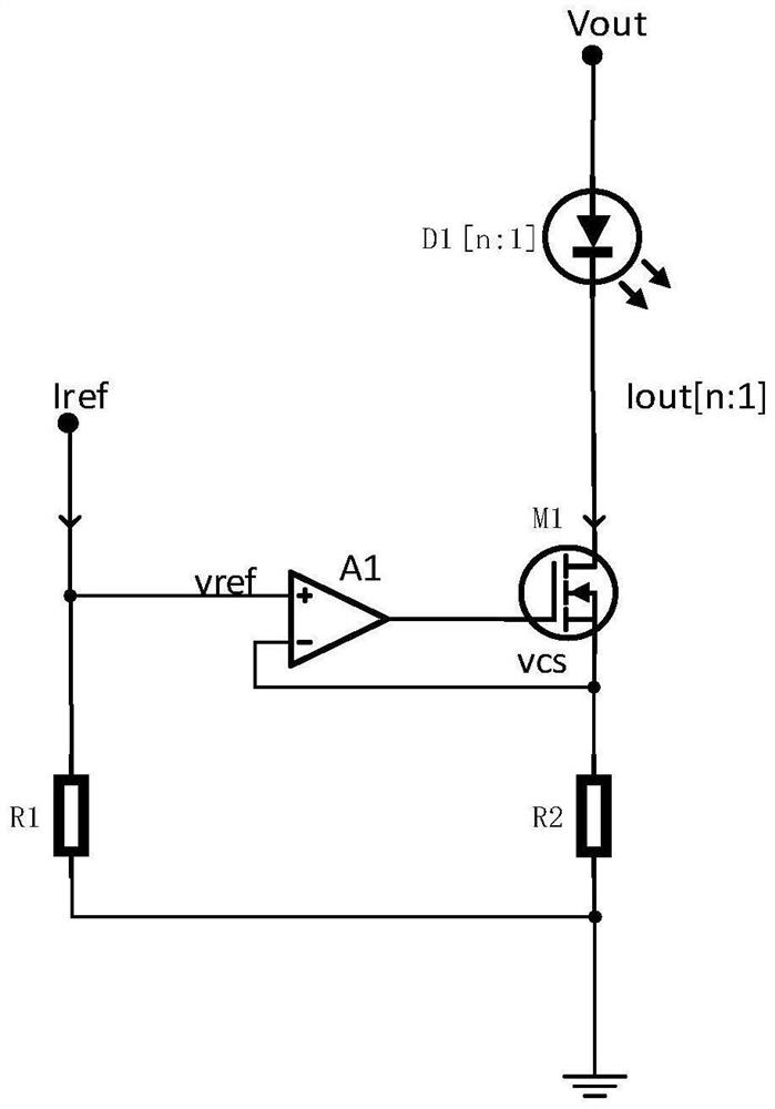
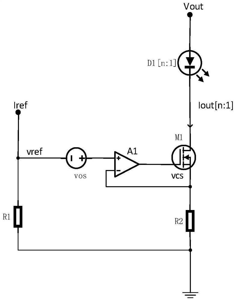
[0003] In view of the shortcomings of the existing methods, this application proposes an LED drive circuit, a backlight module, and a display device to solve the technical problem that the current of the existing LED drive circuit cannot meet the precision requirements when the current is small.

Method used


Image

  • LED drive circuit, backlight module and display device
  • LED drive circuit, backlight module and display device
  • LED drive circuit, backlight module and display device

Examples


Embodiment Construction

[0056] The present application is described in detail below, and examples of embodiments of the present application are shown in the drawings, wherein the same or similar reference numerals denote the same or similar components or components having the same or similar functions throughout. Also, detailed descriptions of known technologies will be omitted if they are not necessary to illustrate the features of the present application. The embodiments described below by referring to the figures are exemplary only for explaining the present application, and are not construed as limiting the present application.

[0057] Those skilled in the art can understand that, unless otherwise defined, all terms (including technical terms and scientific terms) used herein have the same meanings as commonly understood by those of ordinary skill in the art to which this application belongs. It should also be understood that terms, such as those defined in commonly used dictionaries, should be ...


PUM


Abstract

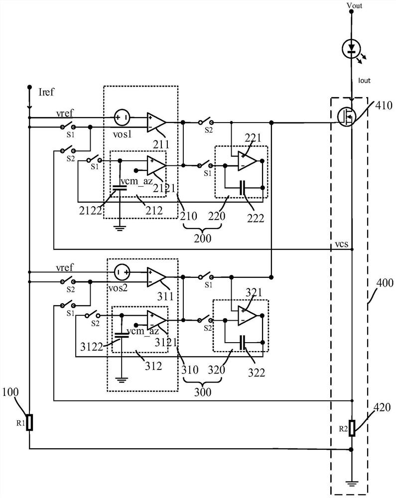
The invention provides an LED drive circuit, a backlight module and a display device. The LED driving circuit comprises a voltage generation unit, a switching circuit, a first control module, a second control module and a driving unit, each of the first control module and the second control module comprises a transconductance amplifier group and an operational amplifier unit, and alternately works in a calibration stage and a control stage based on connection and disconnection of a switching circuit; the driving unit generates working voltage based on the first voltage and provides driving current for the LED based on the working voltage; the transconductance amplifier group receives a reference voltage and a working voltage in a control stage and outputs a first voltage to the driving unit after internal compensation, and the operational amplifier unit is in an off state in the control stage; the transconductance amplifier group receives the reference voltage and stores the calibration voltage in the calibration stage, outputs a second voltage to the operational amplifier unit based on the calibration voltage, and performs internal compensation based on the calibration voltage in the control stage; the operational amplifier unit enables the second voltage to be equal to the first voltage in the calibration stage.

Description

technical field [0001] The present application relates to the technical field of semiconductors, and in particular, the present application relates to an LED driving circuit, a backlight module, and a display device. Background technique [0002] In LCD (Liquid Crystal Display, liquid crystal display) devices, a backlight module is required, which is used to provide a backlight for the LCD display panel. The backlight generally uses multiple constant current LEDs (Light Emitting Diode, light emitting diode) Driving circuit; in order to display uniformly on the LCD display panel, the current of each backlight source is required to be equal. In addition, in order to adjust the display brightness of the display panel, it is also necessary to adjust the current of each LED drive circuit from full load to 1% of full load; the adjustment range of the drive current is very wide, when the current of the LED drive circuit is small , current accuracy and matching is a big problem. ...

Claims


Application Information

Patent Timeline
Patent Type & Authority Applications(China)
IPC IPC(8): G09G3/34G09G3/36H05B45/345H05B45/37H05B45/10
CPCY02B20/30
Inventor 赵新江
Owner BEIJING ESWIN COMPUTING TECH CO LTD
Learn More