Transformer body pressing device for power transformer

A technology for power transformers and compression devices, which is applied in the field of transformers, can solve problems such as inability to protect the transformer, limit the body of the device, and damage the transformer, and achieve the effect of improving installation efficiency and simple and convenient installation

Pending Publication Date: 2022-04-12
WUJIANG TRANSFORMER
View PDF0 Cites 0 Cited by
  • Summary
  • Abstract
  • Description
  • Claims
  • Application Information

AI Technical Summary

Problems solved by technology

[0003] The transformer body in the prior art is more troublesome to install, and most of the body is limited when the body is installed. The transformer cannot be protected when the transformer is transported or encounters a large external force in windy weather, which is easy to cause transformer damage

Method used


Image

  • Transformer body pressing device for power transformer
  • Transformer body pressing device for power transformer
  • Transformer body pressing device for power transformer

Examples


Embodiment Construction

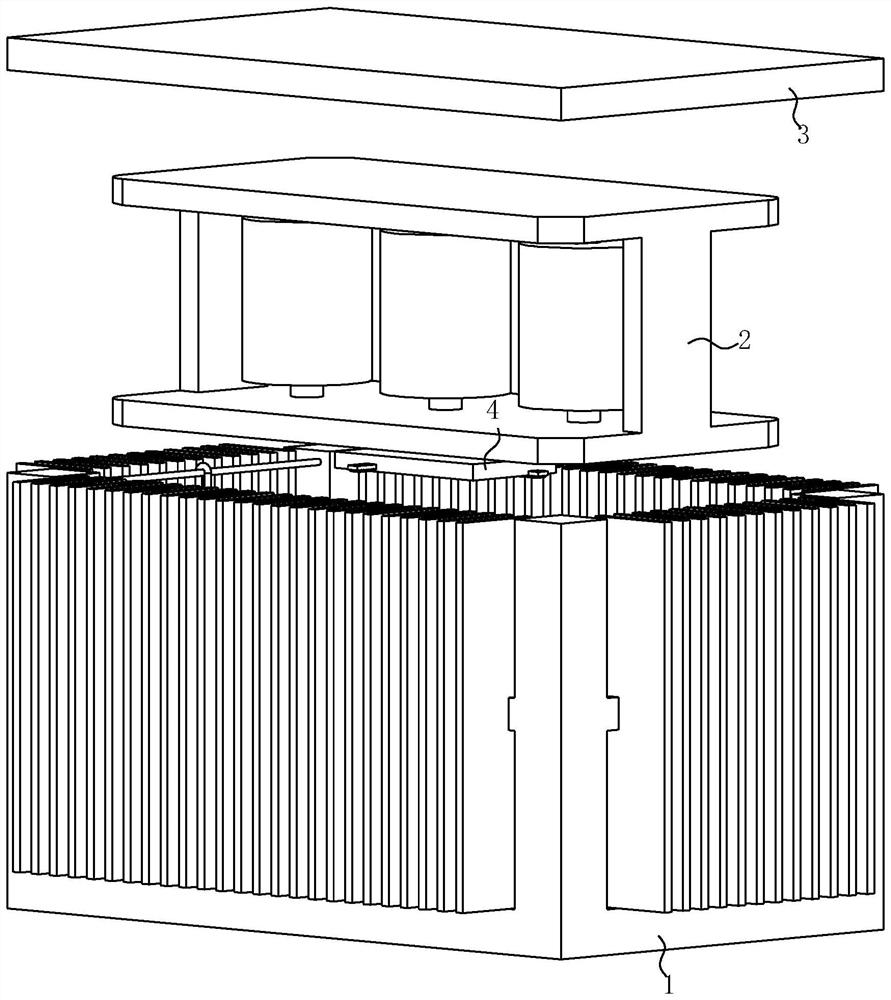
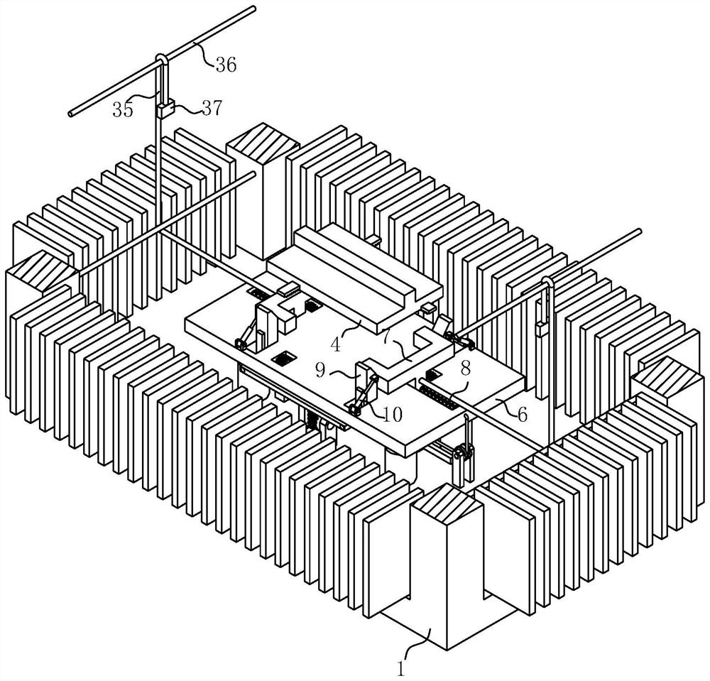
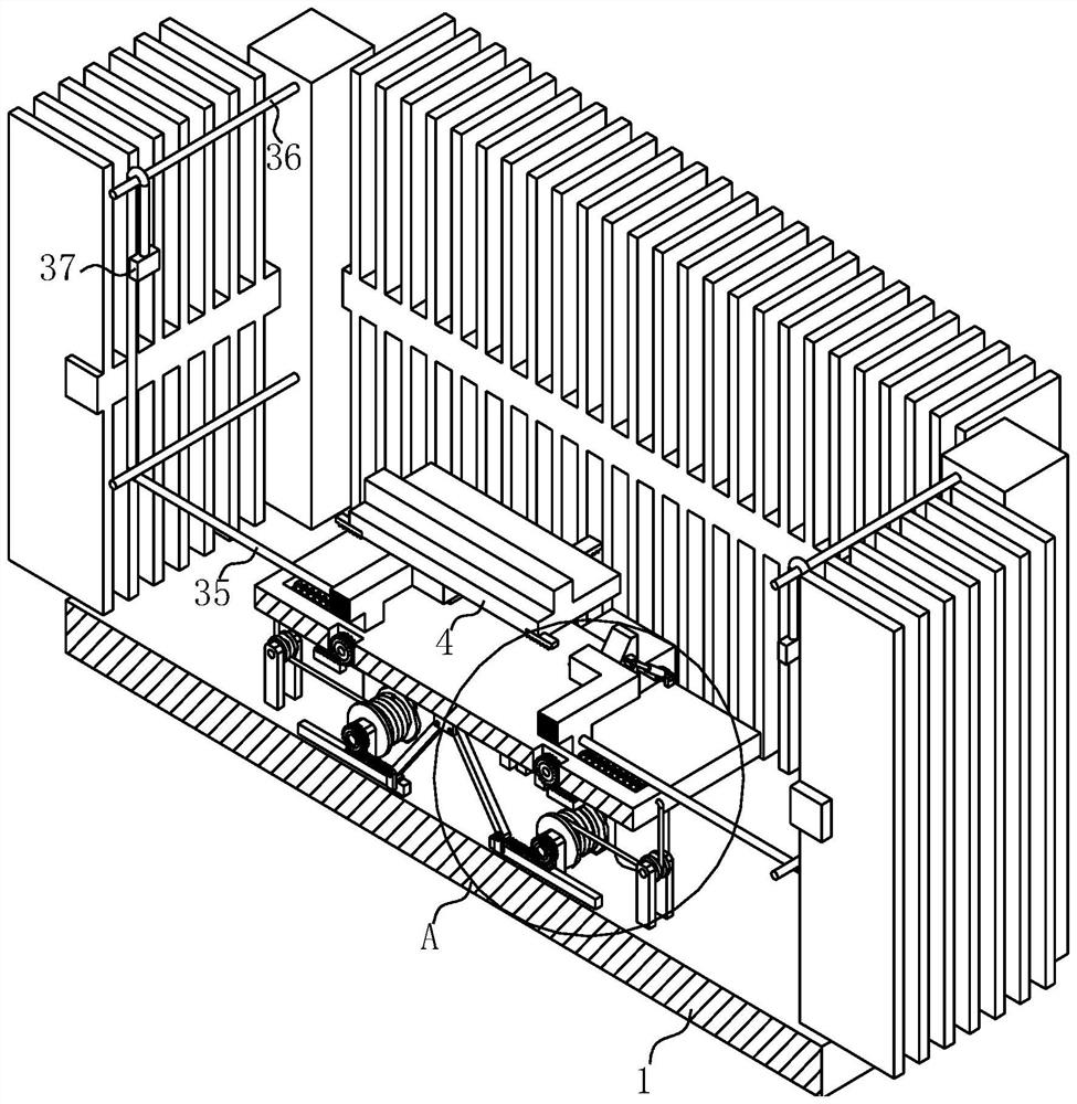
[0029] see Figure 1-9 , the present invention provides a technical solution: a body pressing device for a power transformer, comprising a transformer oil tank 1, a transformer body 2 and a cover plate 3, the bottom of the transformer body 2 is fixedly connected with a T-shaped slider 4 , the bottom of the transformer oil tank 1 is fixedly connected with a first gas spring 5, the top of the first gas spring 5 is fixedly connected with a first fixing plate 6, and the left and right sides of the top of the first fixing plate 6 are slidingly connected There is a C-shaped limiting plate 7, and the two C-shaped limiting plates 7 are respectively used to limit the left and right ends of the T-shaped slider 4; the C-shaped limiting plate 7 is fixedly connected with a The first spring 8, the front and rear sides of the top of the first fixed plate 6 are slidably connected to the limit rods 9, and the two limit rods 9 are used to limit the front and rear ends of the T-shaped slider 4 r...


PUM


Abstract

The device comprises a transformer oil tank, a transformer body and a cover plate, the bottom of the transformer body is fixedly connected with a T-shaped sliding block, and the bottom of the transformer oil tank is fixedly connected with a first gas spring; a first fixing plate is fixedly connected to the top end of the first gas spring, C-shaped limiting plates are slidably connected to the left side and the right side of the top of the first fixing plate correspondingly, and the two C-shaped limiting plates are used for limiting the left end and the right end of a T-shaped sliding block correspondingly; a first spring used for resetting the C-shaped limiting plate is fixedly connected to the C-shaped limiting plate, limiting rods are slidably connected to the front side and the rear side of the top of the first fixing plate correspondingly, the two limiting rods are used for limiting the front end and the rear end of a T-shaped sliding block correspondingly, and the limiting rods are located on the outer side of the C-shaped limiting plate; the transformer body can be installed more easily, and the transformer is more stable in use.

Description

technical field [0001] The invention relates to the technical field of transformers, in particular to a body pressing device for a power transformer. Background technique [0002] The distribution transformer is one of the important equipment in the power supply and distribution system of industrial and mining enterprises and civil buildings. It reduces the 10(6)kV or 35kV network voltage to the 230 / 400V bus voltage used by users. This type of product is suitable for AC 50 (60) Hz, three-phase maximum rated capacity of 2500kVA (single-phase maximum rated capacity of 833kVA, generally not recommended to use single-phase transformers), and can be used indoors (outdoors) when the capacity is 315kVA and below Can be installed on a pole, the ambient temperature is not higher than 40°C, not lower than -25°C, the highest daily average temperature is 30°C, the highest annual average temperature is 20°C, the relative humidity is not more than 90% (ambient temperature is 25°C), the al...

Claims


Application Information

Patent Timeline
IPC IPC(8): H01F27/06H01F27/14F16F15/067
CPCY02T10/62
Inventor 张春红
Owner WUJIANG TRANSFORMER
Why Eureka
Try Eureka