Overcurrent protection circuit and driving circuit of display panel

An overcurrent protection circuit and current technology, which is applied in the direction of emergency protection circuit devices, overcurrent protection, circuit devices, etc., can solve problems such as drive circuit damage, display panel burnout, device damage, etc., to avoid device Loss caused by damage, stable protection effect, good over-current protection effect

Active Publication Date: 2022-04-12
HKC CORP LTD
View PDF6 Cites 0 Cited by
  • Summary
  • Abstract
  • Description
  • Claims
  • Application Information

AI Technical Summary

Problems solved by technology

[0002] The display device includes at least a display panel and a driving circuit. The normal display of the display device is usually controlled by the driving circuit to control the normal operation of the display panel. However, when a large current appears at either end of the driving circuit or the display panel, the driving circuit will damage, or burnout inside the display panel, resulting in product damage
[0003] In the prior art, it is usually by detecting the electrical signal state of the drive circuit or a certain end of the display panel, such as the display panel end. When an abnormal signal at the display panel end is detected, such as a large current, the circuit at the display panel end will be disconnected, but , when the signal at the display panel end is interrupted, the signal state at the drive circuit end will also change instantaneously, which will cause the display panel end to restart the signal supply, which cannot completely cut off the signal supply between the entire lines, and cannot achieve over-current protection well. , there is still the risk of device damage due to overcurrent, therefore, an overcurrent protection circuit that can effectively prevent large currents is urgently needed

Method used


Image

  • Overcurrent protection circuit and driving circuit of display panel
  • Overcurrent protection circuit and driving circuit of display panel
  • Overcurrent protection circuit and driving circuit of display panel

Examples


Embodiment 1

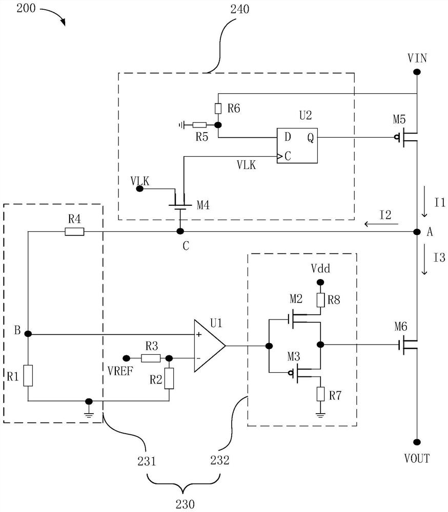
[0050] Figure 2a It is a schematic circuit diagram of an overcurrent protection circuit in the embodiment of the present application, refer to Figure 2a It can be seen that, as the first embodiment of the present application, the first detection module 230 includes a detection unit 231 and a voltage comparison unit U1, the input terminal of the detection unit 231 is connected to one end of the detection branch, and the detection unit 231 flows from the detection branch. The current at the input end of the detection unit 231 is the current I to be detected; the output end of the detection unit 231 is connected to the first input end of the voltage comparison unit U1, and the received current I to be detected is converted into a first detection voltage and sent to the voltage comparison unit Unit U1; the second input terminal of the voltage comparison unit U1 is connected to the first reference voltage VREF, and the output terminal of the voltage comparison unit U1 is connecte...

Embodiment 2

[0069] Figure 3a It is a schematic circuit diagram of the overcurrent protection circuit of Embodiment 2 of the present application. Referring to FIG. 3, it can be seen that as Embodiment 2 of the present application, the difference from Embodiment 1 is that the detection unit 231 also includes a first resistor R1 and a first switch M1 , one end of the first resistor R1 is connected to one end of the detection branch, and the current flowing into the first resistor R1 from the detection branch is the current I to be detected; the other end of the first resistor R1 is grounded; the control terminal of the first switch M1 is connected to Between the detection branch and the first resistor R1; the input end of the first switch M1 is connected to the second reference voltage Vb; the output end of the first switch M1 is grounded; the first input end of the voltage comparison unit U1 is connected to the first switch The input terminal of M1, the voltage at the input terminal of the...

Embodiment 3

[0078] Figure 4a It is the circuit schematic diagram of the overcurrent protection circuit of the third embodiment of the present application, refer to Figure 4a It can be seen that, as the third embodiment of the present application, the difference from the first embodiment is that the detection unit 231 includes a transistor T1, the base of the transistor T1 is connected to one end of the detection branch, and the power flowing into the transistor T1 from the detection branch is The current of the base is the current I to be detected; the emitter of the transistor T1 receives the second reference voltage Vb; the collector of the transistor T1 is grounded; the first input terminal of the voltage comparison unit U1 is connected to the emitter of the transistor T1, The voltage of the emitter of the transistor T1 is the first detection voltage.

[0079] In this embodiment, the current change is converted into the first detection voltage through the transistor T1, and the tran...


PUM


Abstract

The invention discloses an overcurrent protection circuit and a driving circuit of a display panel. The overcurrent protection circuit comprises a first control module, a second control module, a detection branch, a first detection module and a second detection module, one end of the detection branch is connected between the first control module and the second control module, and the other end is connected to the input ends of the first detection module and the second detection module; the current on the detection branch is the current to be detected, and when the first detection module detects that the current to be detected is smaller than a preset first threshold value, the second control module is controlled to be switched off to disconnect the load end; and when the second detection module detects that the current to be detected is greater than a preset second threshold value, the first control module is controlled to be switched off, and the power supply end is switched off. According to the over-current protection circuit, the problem that large current occurs at any one of the power supply end or the load end is solved, and the whole driving circuit can be turned off through the over-current protection circuit, so that over-current protection is realized.

Description

technical field [0001] The present application relates to the field of display technology, in particular to an overcurrent protection circuit and a driving circuit of a display panel. Background technique [0002] The display device includes at least a display panel and a driving circuit. The normal display of the display device is usually controlled by the driving circuit to control the normal operation of the display panel. However, when a large current appears at either end of the driving circuit or the display panel, the driving circuit will damage, or burnout inside the display panel, resulting in damage to the product. [0003] In the prior art, it is usually by detecting the electrical signal state of the drive circuit or a certain end of the display panel, such as the display panel end. When an abnormal signal at the display panel end is detected, such as a large current, the circuit at the display panel end will be disconnected, but , when the signal at the display...

Claims


Application Information

Patent Timeline
Patent Type & Authority Applications(China)
IPC IPC(8): H02H3/08H02H3/05
Inventor 卓恩宗张合静
Owner HKC CORP LTD
Why Eureka
Try Eureka