

Data transmission method, device, equipment and power utilization system
A transmission method and data technology, applied in the field of data transmission, can solve the problem of high power consumption of the controller, and achieve the effect of reducing power consumption and relieving communication pressure.
Active Publication Date: 2022-04-12
GREE ELECTRIC APPLIANCES INC
View PDF8 Cites 0 Cited by
- Summary
- Abstract
- Description
- Claims
- Application Information
AI Technical Summary
Problems solved by technology
[0004] In view of this, the purpose of the present invention is to provide a data transmission method, device, equipment and power system, to overcome the current power system controller Big problem
Method used
View moreImage
Smart ImageViewing Examples

Examples
Embodiment
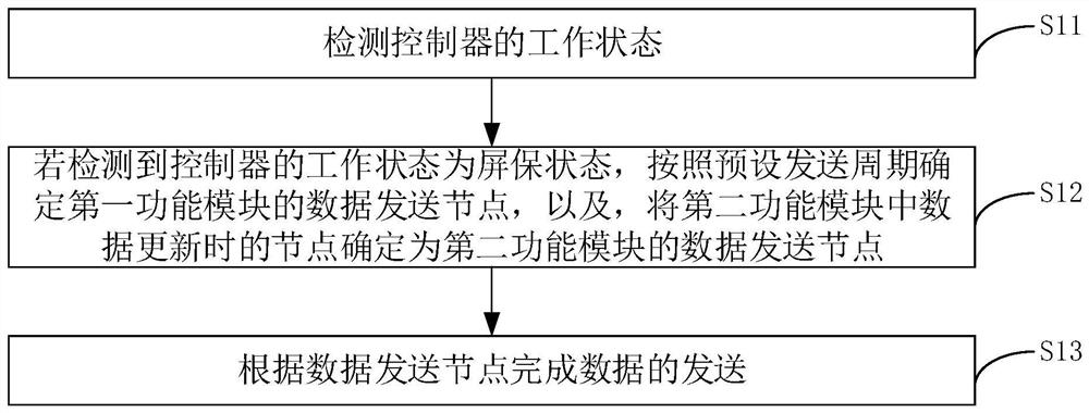
[0044] figure 1 It is a flow chart of an embodiment of a transmission method of data of the present invention. See figure 1 This embodiment can include the following steps:
[0045] S11, the operating state of the detection controller.
Login to View More PUM
 Abstract
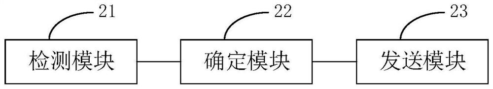
The invention relates to the technical field of data transmission, in particular to a data transmission method, device and equipment and a power utilization system.The method comprises the steps that when a controller is in a screensaver state, data are not sent in a unified mode any more, but a data sending node of a first function module is determined according to a preset sending period; and determining a node in the second function module when the data is updated as a data sending node of the second function module so as to complete data sending according to the data sending node. A user can set the first function module and the second function module according to the importance degree of the modules, and data in the second function module is sent only when being updated, so that the data of all the function modules are prevented from being frequently sent in a bus, the power consumption of the controller is reduced, and the communication pressure of the bus is relieved.
Description
Technical field [0001] The present invention relates to the field of data transmission, and more particularly to a transmission method, apparatus, device, and electrical system of data. Background technique [0002] Large electrical systems typically include controllers and multiple controlled work devices, controls between controllers, and work devices typically transmitted over communication bus. During the work, there is a lot of data to convey on the bus, but there is a part of the necessary data, not only increase the communication pressure of the bus, but also increase the controller power consumption. For example, the current data transmission mode of the current large central air conditioner is as follows: Whether it is frequent in operation or operation, hundreds of data will be sent on the bus according to the prescribed cycle; the data is immediately on the bus. Send; single system mode is still transmitted according to the multi-system mode data volume loop. Moreover,...
Claims
Login to View More Application Information
Patent Timeline
 Patent Type & AuthorityApplications(China)
IPC IPC(8): H04L12/10H04L12/40H04L67/1001H04L67/12
Inventor杨敏恒关富文唐政清董玉红
OwnerGREE ELECTRIC APPLIANCES INC