Phase difference plate, and circularly polarizing plate, liquid crystal display device, and organic EL display device provided with same
A technology of retardation plate and circular polarizing plate, which is applied in the field of retardation plate and can solve the problem of not functioning in the visible light region
Pending Publication Date: 2022-04-12
NIPPON KAYAKU CO LTD +1
View PDF8 Cites 0 Cited by
- Summary
- Abstract
- Description
- Claims
- Application Information
AI Technical Summary
Problems solved by technology
[0004] The retardation plate used in this circular polarizing plate has conventionally had the following problem due to the wavelength dependence (wavelength dispersion) of the retardation value: when used to prevent reflection of an organic EL display device, the retardation plate for each wavelength in the visible light region The band does not function as a λ / 4 plate, and produces coloration in a dark state (black screen)
The above problems become especially noticeable when viewing the display device with an oblique viewing angle
Method used
View moreImage
Smart ImageViewing Examples

Examples
Embodiment 1
[0118] Example 1: (in order from the incident light side) polarizing element, first optically anisotropic layer, third optically anisotropic layer 1, second optically anisotropic layer, reflecting plate
Embodiment 2
[0119] Example 2: (in order from the incident light side) polarizing element, first optically anisotropic layer, third optically anisotropic layer 2, second optically anisotropic layer, reflecting plate
Embodiment 3
[0120] Example 3: (in order from the incident light side) polarizing element, first optically anisotropic layer, third optically anisotropic layer 3, second optically anisotropic layer, reflecting plate
Login to View More PUM
| Property | Measurement | Unit |
|---|---|---|
| thickness | aaaaa | aaaaa |
| thickness | aaaaa | aaaaa |
| thickness | aaaaa | aaaaa |
Abstract
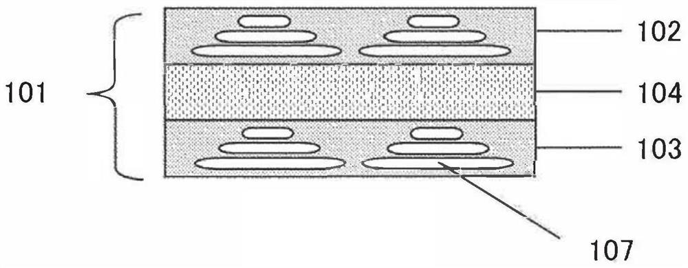
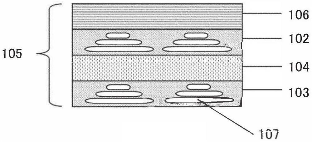
Provided is a phase difference plate provided with: a first optically anisotropic layer in which a rod-like liquid crystal compound is aligned with the thickness direction as the spiral axis and which has an in-plane phase difference value (Re) substantially equal to 1 / 2 wavelength; and a second optically anisotropic layer which is an optically anisotropic layer in which the rod-like liquid crystal compound is aligned with the thickness direction as a spiral axis and which has an in-plane phase difference (Re) substantially equal to 1 / 4 wavelength. Wherein a third optically anisotropic layer, which satisfies the following formula (1), is provided between the first and second optically anisotropic layers: nxnult; nz (1) (In the formula, nx and ny represent refractive indexes in orthogonal plate plane directions, and nz represents a refractive index in a direction perpendicular to the plate plane direction).
Description
technical field [0001] The present invention relates to a retardation plate useful for a liquid crystal display device and an organic EL display device, and a circularly polarizing plate, a liquid crystal display device, and an organic EL display device having the retardation plate. Background technique [0002] The retardation plate for circularly polarizing plates is used in a wide range of applications for flat-panel displays. [0003] Conventionally, with regard to image display panels and the like, there has been proposed a method of arranging a circular polarizer on the surface of the image display panel, and reducing reflection of external light by the circular polarizer. This circular polarizing plate is composed of a linear polarizing plate and a 1 / 4 wavelength retardation plate (hereinafter also referred to as a λ / 4 plate). The linear polarizing plate converts the external light toward the display surface of the image display panel into linear polarized light. , a...
Claims
Login to View More Application Information
Patent Timeline
 Patent Type & Authority Applications(China)
IPC IPC(8): G02B5/30G02F1/1335G02F1/13363G02F1/137H01L27/32
CPCG02B5/30G02F1/1335G02F1/13363G09F9/00G09F9/30H05B33/02H10K59/8791G02B5/3083G02F1/133528
Inventor 久住贵大中村大辅J·W·维尼玛
Owner NIPPON KAYAKU CO LTD