Method for driving plasma display panel, and plasma display apparatus

A technology for display panels and driving methods, applied to static indicators, instruments, etc., can solve problems such as increased impedance and unstable writing action

Inactive Publication Date: 2013-08-14
PANASONIC CORP
View PDF8 Cites 0 Cited by
  • Summary
  • Abstract
  • Description
  • Claims
  • Application Information

AI Technical Summary

Problems solved by technology

[0015] In a large-screen panel that achieves high definition, not only the number of electrodes that must be driven increases, but also the impedance at the time of driving increases, so the write operation tends to become unstable

Method used


Image

  • Method for driving plasma display panel, and plasma display apparatus
  • Method for driving plasma display panel, and plasma display apparatus
  • Method for driving plasma display panel, and plasma display apparatus

Examples


Embodiment approach 1

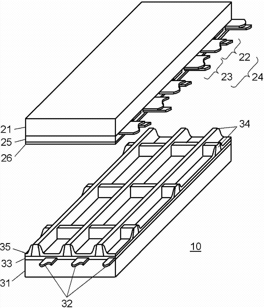
[0060] figure 1 It is an exploded perspective view showing the configuration of panel 10 used in the plasma display device according to Embodiment 1 of the present invention.

[0061] On front substrate 21 made of glass, a plurality of display electrode pairs 24 including scan electrodes 22 and sustain electrodes 23 are formed. Furthermore, dielectric layer 25 is formed to cover scan electrodes 22 and sustain electrodes 23 , and protective layer 26 is formed on dielectric layer 25 .

[0062] In order to facilitate discharge in the discharge cells, protective layer 26 is formed of a material having high electron emission performance, that is, a material mainly composed of magnesium oxide (MgO).

[0063] The protective layer 26 may consist of one layer, or may consist of multiple layers. In addition, a structure in which particles exist on a layer may also be used.

[0064] A plurality of data electrodes 32 are formed on rear substrate 31 , a dielectric layer 33 is formed to ...

Embodiment approach 2

[0245] In Embodiment 1, an example was described in which panel 10 was driven by setting the number of times of performing the initialization operation for all the cells once in one field. However, the present invention is not limited to these configurations. For example, it is also possible to apply to a configuration in which panel 10 is driven by setting the number of times of performing the initialization operation for all cells once in a plurality of fields, and in this case, the same effect as above can be obtained as well.

[0246] In the driving method in which the number of times of performing the initialization operation of all the cells is set once in a plurality of fields, compared with the configuration in which the initialization operation of all the cells is performed once in one field, it is possible to reduce the noise caused by the initialization operation of all the cells. By emitting light, the black luminance (the luminance of gradation without sustain dis...

Embodiment approach 3

[0362] In Embodiment 1 and Embodiment 2, the configuration in which the maximum voltage of the upward erasing ramp voltage L3 is set to the voltage Vr lower than the voltage Vs in all subfields has been described. However, the present invention is not limited to these configurations, and may be a configuration that generates an upward erasing ramp voltage that rises to a voltage equal to or higher than the voltage Vs.

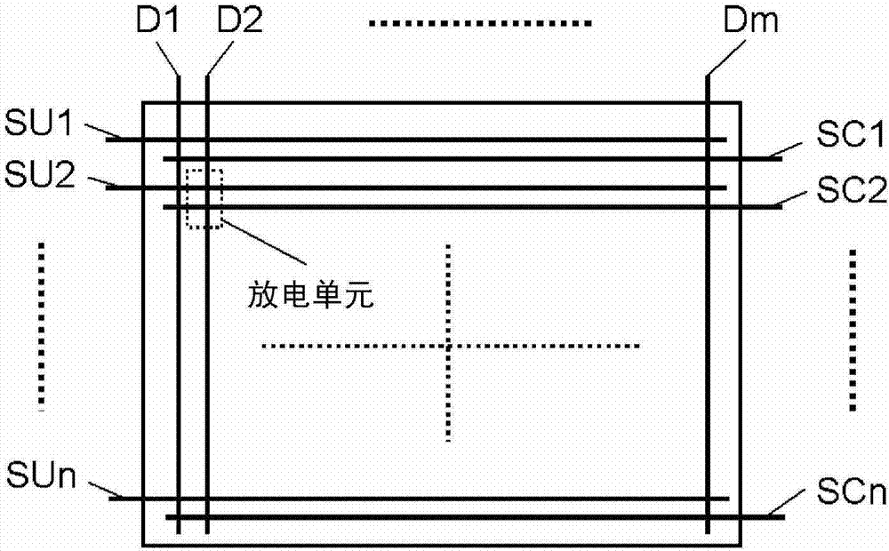
[0363] The inventors of the present application have confirmed that, in the last subfield of one field, by applying an up-ramp waveform voltage rising to a voltage Vs or higher to scan electrodes SC1 - SCn instead of up-erase ramp voltage L3 , more stable A write action is generated.

[0364] This is considered to be because, in a subfield with a large number of sustain pulses generated in the sustain period, wall charges and trigger particles generated in the sustain operation are excessive, and therefore setting the erasing operation relatively large can stab...


PUM


Abstract

A stable write operation is performed during driving of a high-definition large-screen plasma display panel. The following field is therefore generated in a method for driving a plasma display panel in which a plurality of displaying combinations used to display gradations is selected from among a plurality of combinations having different combinations of light-emitting subfields and non-light-emitting subfields, the selected displaying combinations are designated as a set, a single displaying combination is selected from the set, and light emission or non-emission of discharge cells is controlled. The field has a subfield in which an upwardly inclined waveform voltage that increases from a base electric potential to a first predetermined voltage is applied to a scanning electrode after the final sustain pulse is generated in a sustain period, on the basis of the displaying combination included in the set of displaying combinations. The field also has a specific subfield in which a downwardly inclined waveform voltage that decreases from a base electric potential to a second predetermined voltage is applied to the scanning electrode after the final sustain pulse is generated in a sustain period, and an upwardly inclined waveform voltage is then applied to the scanning electrode.

Description

technical field [0001] The present invention relates to a plasma display device using an AC surface discharge type plasma display panel and a driving method for the plasma display panel. Background technique [0002] A representative AC surface discharge panel as a plasma display panel (hereinafter, abbreviated as "panel") has a plurality of discharge cells formed between a front substrate and a rear substrate that are arranged to face each other. [0003] In the front substrate, a plurality of pairs of display electrodes including a pair of scan electrodes and sustain electrodes are formed parallel to each other on the glass substrate on the front side. And, a dielectric layer and a protection layer are formed to cover these display electrode pairs. [0004] In the rear substrate, a plurality of parallel data electrodes are formed on a glass substrate on the rear side, a dielectric layer is formed to cover these data electrodes, and a plurality of barrier ribs are formed o...

Claims


Application Information

Patent Timeline
IPC IPC(8): G09G3/294G09G3/293
CPCG09G2330/021G09G2310/066G09G3/2942G09G3/2029G09G2320/0673G09G3/293
Inventor 折口贵彦盐崎裕也斋藤鲇彦富冈直之庄司秀彦
Owner PANASONIC CORP
Why Eureka
Try Eureka