Liquid crystal panel and liquid crystal display device

A liquid crystal panel and liquid crystal layer technology, applied in the direction of instruments, polarizing elements, optics, etc., can solve the problems of large light leakage, low contrast, color shift and other problems of black display, and achieve the advantages of suppressing red coloring, reducing black brightness, and excellent visual recognition Effect

Active Publication Date: 2021-02-02
NITTO DENKO CORP
View PDF24 Cites 0 Cited by
  • Summary
  • Abstract
  • Description
  • Claims
  • Application Information

AI Technical Summary

Problems solved by technology

[0005] The IPS liquid crystal display device shows a large amount of light leakage when viewed from an oblique direction at an angle of 45 degrees relative to the absorption axis of the polarizer (azimuth angles of 45 degrees, 135 degrees, 225 degrees, and 315 degrees). , easy to produce contrast reduction or color shift

Method used


Image

  • Liquid crystal panel and liquid crystal display device
  • Liquid crystal panel and liquid crystal display device
  • Liquid crystal panel and liquid crystal display device

Examples


no. 1 approach

[0120]

[0121] (adjustment of chroma)

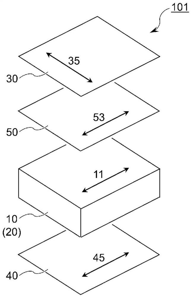
[0122] Figure 12 is based on figure 1 The simulation results of the O-mode liquid crystal panel 101 shown are graphs plotting the conditions under which the chromaticity of black display becomes a specific value. The horizontal axis is the retardation Ct in the thickness direction at a wavelength of 650nm in the red transmission region of the color filter 650 , the vertical axis is the thickness retardation Rt of the wavelength 650nm of the optical anisotropic component 650 . in each Ct 650 , the point where the chromaticity u' of black display becomes 0.35 in the direction of the azimuth angle of 45° and the polar angle of 60° is represented by a black circle mark and a black triangle mark. at Rt. 650 When u' is more than 0.35 when located between the blacked-in circle mark and the blacked-out triangular mark, the black display is colored red and visually confirmed. at Rt. 650 When it is located above the blacked-in circle ...

no. 2 approach

[0169]

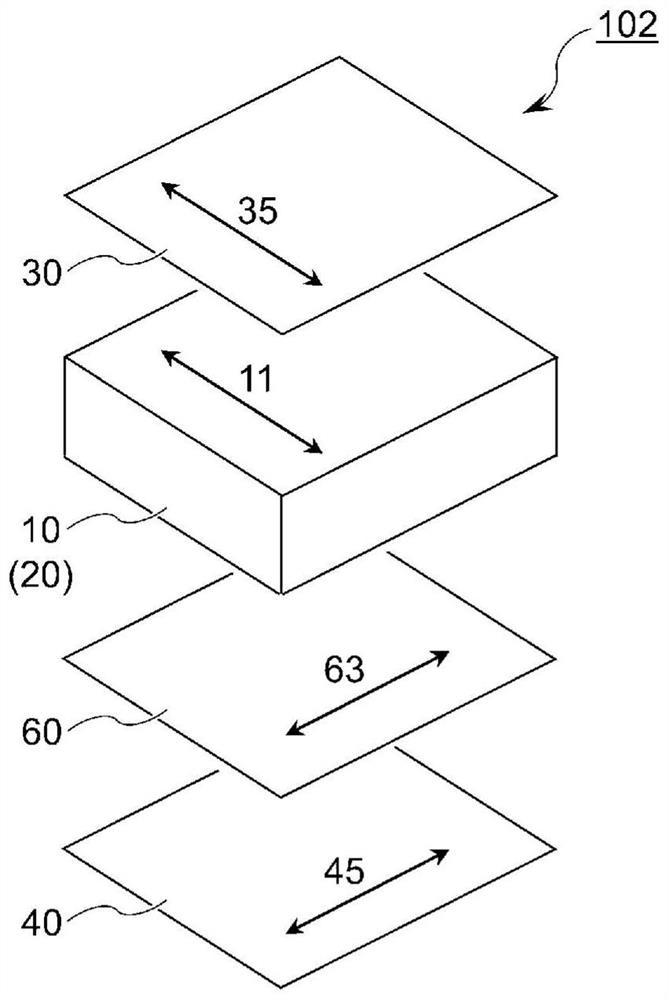
[0170] Figure 14 is based on image 3 The simulation results of the liquid crystal panel 102 in the E-mode shown are graphs showing the conditions under which the chromaticity of black display becomes a specific value. and Figure 12 Similarly, the point where the black display chromaticity u' in the direction of the azimuth angle of 45° and the polar angle of 60° becomes 0.35 is indicated by a black circle mark and a black triangle mark, and the black display chromaticity u' The point at which it becomes 0.314 is indicated by a white circle mark and a white triangle mark.

[0171] and Figure 12 In the same way, Figure 14 Among them, the boundary of u'=0.35 can also be approximated by a straight line represented by the following formula (6) and formula (7):

[0172] Rt 650 =0.37 (Ct 650 )+116...(6)

[0173] Rt 650 =-0.44 (Ct 650 )+120...(7).

[0174] Therefore, in the liquid crystal panel 102, the retardation Ct in the thickness direction of the wavele...


PUM

PropertyMeasurementUnit
thicknessaaaaaaaaaa

Abstract

A liquid crystal panel (101) is provided with a liquid crystal cell (20), a first polarizer (30), a second polarizer (40), and an optically anisotropic element (50). The liquid crystal cell is provided with a liquid crystal layer including liquid crystal molecules in a homogeneous alignment in the absence of an electric field, and a color filter (22) disposed on a first principal surface of the liquid crystal layer. The slow-axis direction (53) of the optically anisotropic element (50) and the absorption axis direction (45) of the second polarizer are parallel. The thickness-direction retardation of the optically anisotropic element and the thickness-direction retardation of the color filter of the liquid crystal cell satisfy a predetermined relationship for each of a wavelength of 550 nmand a wavelength of 650 nm.

Description

technical field [0001] The invention relates to a liquid crystal panel provided with an optically anisotropic component between a liquid crystal unit and a polarizer. In addition, the present invention relates to a liquid crystal display device using the above liquid crystal panel. Background technique [0002] The liquid crystal panel includes a liquid crystal cell between a pair of polarizers. A liquid crystal cell has a liquid crystal layer between a pair of substrates. In a normal liquid crystal cell, a color filter is provided on a substrate (color filter substrate) disposed on the viewing side of the liquid crystal layer, and a color filter is disposed on a substrate disposed on the light source side. (TFT (thin-film transistor, thin-film transistor) substrate) is provided with pixel electrodes, TFT components, and the like. [0003] In the liquid crystal cell of the transverse electric field effect (IPS, In-Plane Switching) mode, in the state of no electric field, t...

Claims


Application Information

Patent Timeline
Patent Type & Authority Applications(China)
IPC IPC(8): G02F1/13363G02B5/30G02F1/1335
CPCG02B5/30G02F1/13363G02F1/1335G02F1/133528
Inventor 林大辅有贺草平饭田敏行
Owner NITTO DENKO CORP
Why Eureka
Try Eureka