Plasma display device, plasma display system, and method of controlling shutter glass for plasma display device

A display device, plasma technology, applied in alternating current plasma display panels, TV system components, stereoscopic systems, etc.

Inactive Publication Date: 2012-09-05
PANASONIC CORP
View PDF7 Cites 0 Cited by
  • Summary
  • Abstract
  • Description
  • Claims
  • Application Information

AI Technical Summary

Problems solved by technology

However, in the above-mentioned driving method, the light emission in the black display area is only weak light emission when the initializing operation is performed in all the discharge cells.

Method used


Image

  • Plasma display device, plasma display system, and method of controlling shutter glass for plasma display device
  • Plasma display device, plasma display system, and method of controlling shutter glass for plasma display device
  • Plasma display device, plasma display system, and method of controlling shutter glass for plasma display device

Examples


Embodiment approach

[0033] figure 1 It is an exploded perspective view showing the structure of panel 10 used in the plasma display device according to one embodiment of the present invention. A plurality of display electrode pairs 24 including scan electrodes 22 and sustain electrodes 23 are formed on front substrate 21 made of glass. Furthermore, dielectric layer 25 is formed to cover scan electrodes 22 and sustain electrodes 23 , and protective layer 26 is formed on dielectric layer 25 . The protective layer 26 is formed of a material mainly composed of magnesium oxide (MgO).

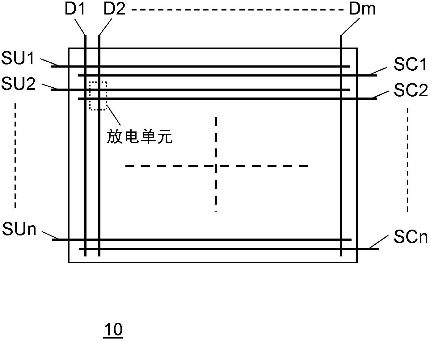
[0034] A plurality of data electrodes 32 are formed on rear substrate 31 , and dielectric layer 33 is formed to cover data electrodes 32 , and rib-shaped partition walls 34 are formed on dielectric layer 33 . Further, phosphor layers 35 that emit light in each color of red (R), green (G), and blue (B) are provided on the side surfaces of the barrier ribs 34 and the dielectric layer 33 .

[0035] These front substrate...


PUM


Abstract

In order to improve image display quality of a plasma display device capable of displaying stereo vision images, the plasma display device comprises a driving circuit that drives a plasma display panel such that right-eye fields and left-eye fields, each being composed of an entire-cell initializing subfield and selected-cell initializing subfields, are alternately repeated while the entire-cell initializing subfield is set as the leading subfield of each field; and a timing generating circuit that generates timing signals for opening and closing shutters including timing signals for opening and closing a right-eye shutter turned on in accordance with the right-eye fields and those for opening and closing a left-eye shutter turned on in accordance with the left-eye fields. The timing signal for opening and closing the shutters are generated such that the timing signals for opening and closing the right-eye shutter and those for opening and closing the left-eye shutter are both turned off during entire-cell initializing periods of the right-eye fields and those of the left-eye fields.

Description

technical field [0001] The present invention relates to a plasma display device, a plasma display system, and shutter glasses for a plasma display device capable of stereoscopically viewing a stereoscopic image composed of right-eye images and left-eye images alternately displayed on a plasma display panel using shutter glasses control method. Background technique [0002] As a representative AC surface discharge type panel of a plasma display panel (hereinafter referred to simply as "panel"), a front substrate on which a plurality of display electrode pairs consisting of a pair of scan electrodes and a sustain electrode is formed, and a front substrate on which a plurality of display electrode pairs are formed The rear substrates of each data electrode are arranged opposite to each other, and a plurality of discharge cells are formed between them. Then, ultraviolet rays are generated by gas discharge in the discharge cells, and phosphors of red, green, and blue colors are ...

Claims


Application Information

Patent Timeline
Patent Type & Authority Applications(China)
IPC IPC(8): G09G3/288H04N13/04G09G3/28G09G3/291G09G3/292G09G3/293G09G3/294G09G3/298
CPCG09G3/003G09G3/2927G09G2320/0238H04N5/66H04N13/341H04N13/398G09G3/28H01J11/10
Inventor 盐崎裕也折口贵彦庄司秀彦石塚光洋木子茂雄
Owner PANASONIC CORP
Why Eureka
Try Eureka