Plasma display device, plasma display system, and control method for shutter glasses for plasma display device

A display device, plasma technology, applied in the direction of static indicators, instruments, etc.

Inactive Publication Date: 2012-10-03
PANASONIC CORP
View PDF7 Cites 0 Cited by
  • Summary
  • Abstract
  • Description
  • Claims
  • Application Information

AI Technical Summary

Problems solved by technology

In addition, if the number of images displayed on the panel per unit time decreases, flickering of images called flicker (flicker) becomes easy to be seen.

Method used


Image

  • Plasma display device, plasma display system, and control method for shutter glasses for plasma display device
  • Plasma display device, plasma display system, and control method for shutter glasses for plasma display device
  • Plasma display device, plasma display system, and control method for shutter glasses for plasma display device

Examples


Embodiment approach

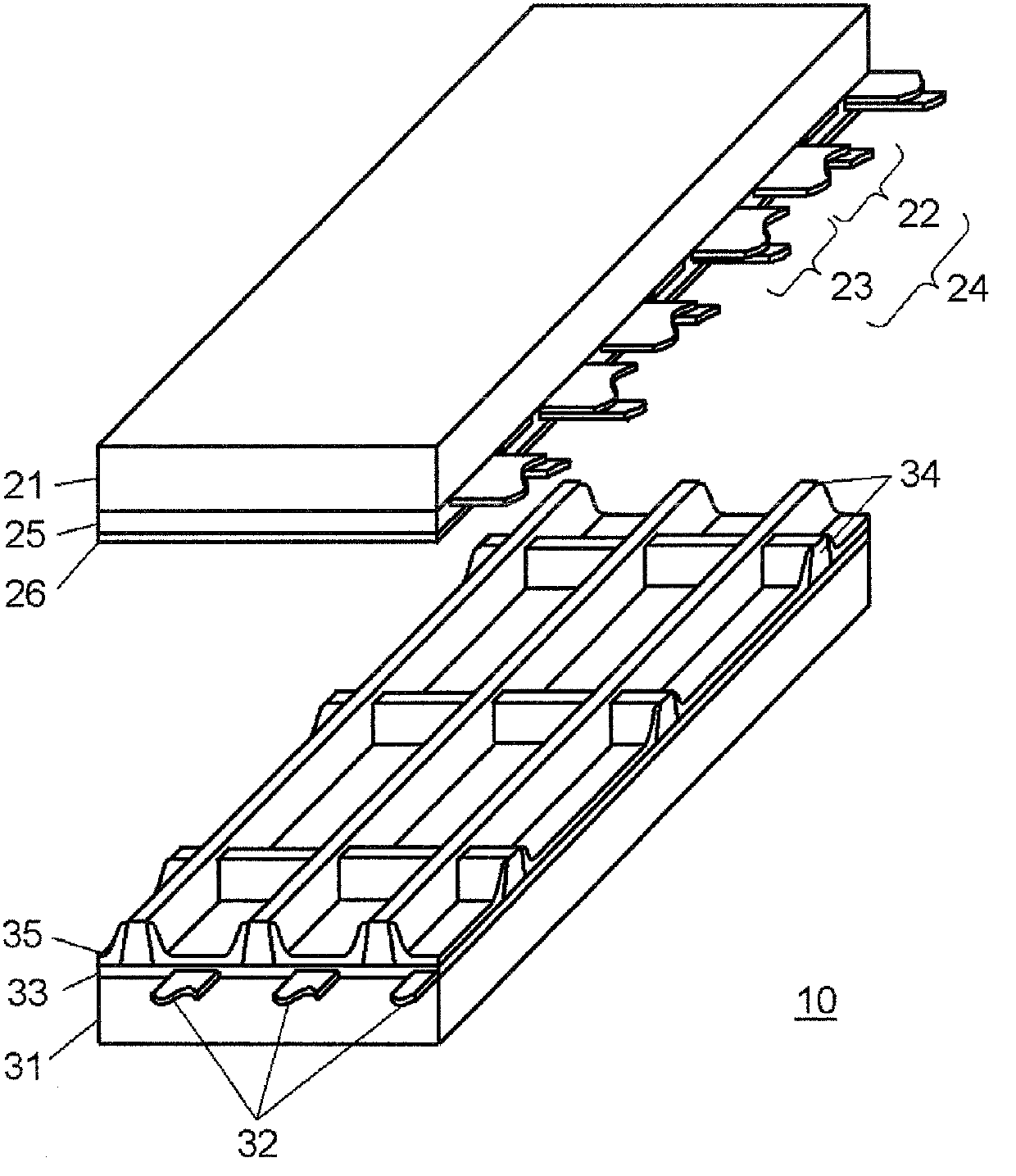
[0040] figure 1 It is an exploded perspective view showing the structure of panel 10 used in the plasma display device according to one embodiment of the present invention. On the front substrate 21 made of glass, a plurality of display electrode pairs 24 composed of scan electrodes 22 and sustain electrodes 23 are formed. In addition, a dielectric layer 25 is formed so as to cover the scan electrode 22 and the sustain electrode 23, and a protective layer 26 is formed on the dielectric layer 25.

[0041] The protective layer 26 is made of a material containing magnesium oxide (MgO) as the main component in order to reduce the discharge start voltage in the discharge cell. Magnesium oxide (MgO) has been used as a material for the panel, and neon (Ne ) And xenon (Xe) gas have a large secondary electron emission coefficient and excellent durability.

[0042] A plurality of data electrodes 32 are formed on the back substrate 31, a dielectric layer 33 is formed so as to cover the data ...


PUM


Abstract

Disclosed is a plasma display device in which write operations are stabilised and crosstalk is reduced while providing excellent contrast when displaying 3D images on a plasma display panel. The plasma display device is provided with: a drive circuit which drives a plasma display panel by carrying out an all-cell initialisation operation during an initialisation period and setting a sub-field which generates a sustain discharge in all discharge cells during a sustain period as the first sub-field in each field; and a control signal generation circuit which generates a shutter open / close timing signal comprising a right-eye timing signal which is ON when a right-eye field is to be displayed and a left-eye timing signal which is ON when a left-eye signal is to be displayed. The shutter open / close timing signal is generated so that the right-eye timing signal and the left-eye timing signal are both OFF during the first sub-field period.

Description

Technical field [0001] The present invention relates to a plasma display device, a plasma display system, and shutter glasses for a plasma display device that can stereoscopically view a stereoscopic image composed of a right-eye image and a left-eye image alternately displayed on a plasma display panel using shutter glasses Control Method. Background technique [0002] An AC surface discharge type panel, which is representative of a plasma display panel (hereinafter abbreviated as "panel"), has a plurality of discharge cells formed between a front substrate and a rear substrate that are opposed to each other. In the front substrate, a plurality of display electrode pairs composed of a pair of scan electrodes and sustain electrodes are formed parallel to each other on a glass substrate on the front side. In addition, a dielectric layer and a protective layer are formed so as to cover these display electrode pairs. [0003] The back substrate has a plurality of parallel data elect...

Claims


Application Information

Patent Timeline
Patent Type & Authority Applications(China)
IPC IPC(8): G09G3/28G09G3/20G09G3/288G09G3/291G09G3/292G09G3/298
CPCG09G3/003G09G3/288G09G3/28
Inventor 盐崎裕也折口贵彦石塚光洋
Owner PANASONIC CORP
Why Eureka
Try Eureka