
Wax draining equipment

A kind of equipment and wax-draining technology, which is applied in the field of vehicle production equipment, can solve the problems of wax liquid flow, wax liquid spraying dead angle, wax liquid accumulation, etc., and achieve the effects of large wax liquid flow range, uniform wax discharge and strong anti-corrosion ability

Pending Publication Date: 2022-04-15
BEIJING FOTONDAIMLER AUTOMOTIVE
View PDF5 Cites 0 Cited by
  • Summary
  • Abstract
  • Description
  • Claims
  • Application Information

AI Technical Summary

Problems solved by technology

[0002] The vehicles in the related art need to be waxed during production, and the traditional waxing equipment cannot tilt the cab at a large angle, so that the cab cannot make the wax flow during the waxing process, and the wax can only be concentrated near the nozzle. In a small area, not only will the wax liquid accumulate, but also there will be a dead spot where the wax liquid is sprayed on the body sheet metal, and the wax film formed by the cab will not cover enough area, which will affect the anti-corrosion performance of the cab

Method used


Image

  • Wax draining equipment
  • Wax draining equipment
  • Wax draining equipment

Examples


Embodiment Construction

[0025] Embodiments of the present invention are described in detail below, examples of which are shown in the drawings, wherein the same or similar reference numerals designate the same or similar elements or elements having the same or similar functions throughout. The embodiments described below by referring to the figures are exemplary only for explaining the present invention and should not be construed as limiting the present invention.

[0026] In describing the present invention, it should be understood that the terms "center", "longitudinal", "transverse", "length", "width", "thickness", "upper", "lower", "front", " Rear", "Left", "Right", "Vertical", "Horizontal", "Top", "Bottom", "Inner", "Outer", "Axial", "Radial", "Circumferential" The orientation or positional relationship indicated by etc. is based on the orientation or positional relationship shown in the drawings, and is only for the convenience of describing the present invention and simplifying the descriptio...


PUM


Abstract

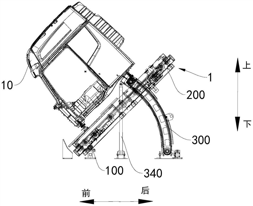
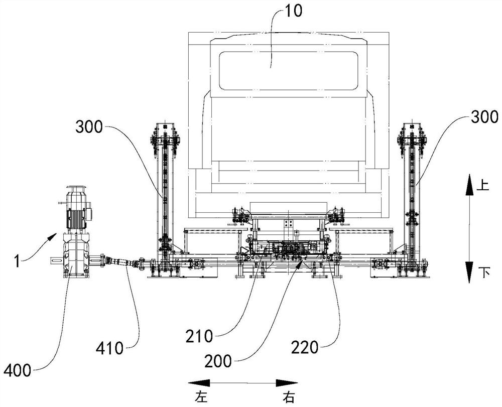
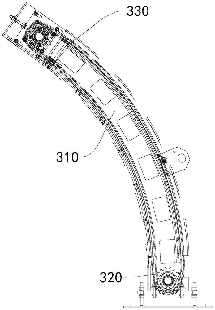
The invention discloses wax draining equipment, which comprises a rotating shaft, a wax draining device and a wax draining device, and the rotating shaft is suitable for being mounted on the ground; the bottom of the cab is suitable for being installed on the roller bed, one side of the roller bed is rotatably installed on the rotating shaft, and the side, away from the rotating shaft, of the roller bed rotates around the rotating shaft to drive the cab to incline; the chain assembly is mounted on one side, far away from the rotating shaft, of the roller bed; and the lifting driving mechanism is connected to the chain assembly, and the lifting driving mechanism drives the chain assembly to rotate so as to drive the other side of the roller bed to rotate around the rotating shaft. The wax draining equipment has the advantages of being large in wax liquid flowing range, uniform in wax draining, high in corrosion resistance and the like.

Description

technical field [0001] The invention relates to the field of vehicle production equipment, in particular to wax removal equipment. Background technique [0002] The vehicles in the related art need to be waxed during production, and the traditional waxing equipment cannot tilt the cab at a large angle, so that the cab cannot make the wax flow during the waxing process, and the wax can only be concentrated near the nozzle. In a small area, not only will the wax liquid accumulate, but also there will be dead spots where the wax liquid is sprayed on the body sheet metal, and the wax film formed by the cab will not cover enough area, which will affect the anti-corrosion performance of the cab. Contents of the invention [0003] The present invention aims to solve at least one of the technical problems existing in the prior art. For this reason, the present invention proposes a kind of wax draining equipment, and this wax draining equipment has the advantages such as large flo...

Claims


Application Information

Patent Timeline
Patent Type & Authority Applications(China)
IPC IPC(8): B05B13/02
Inventor 李利锐边春利陆野王飞杨牧王少猛
Owner BEIJING FOTONDAIMLER AUTOMOTIVE
Learn More