Nail hammer capable of automatically clamping nails
An automatic clamping and nailing technology, used in hand hammers, manufacturing tools, striking tools, etc., can solve the problems of inconvenient work, cracking, and insufficient first strength, so as to improve the nailing effect, improve applicability, and improve efficiency. Effect
- Summary
- Abstract
- Description
- Claims
- Application Information
AI Technical Summary
Problems solved by technology
Method used
Image

Examples
specific Embodiment approach
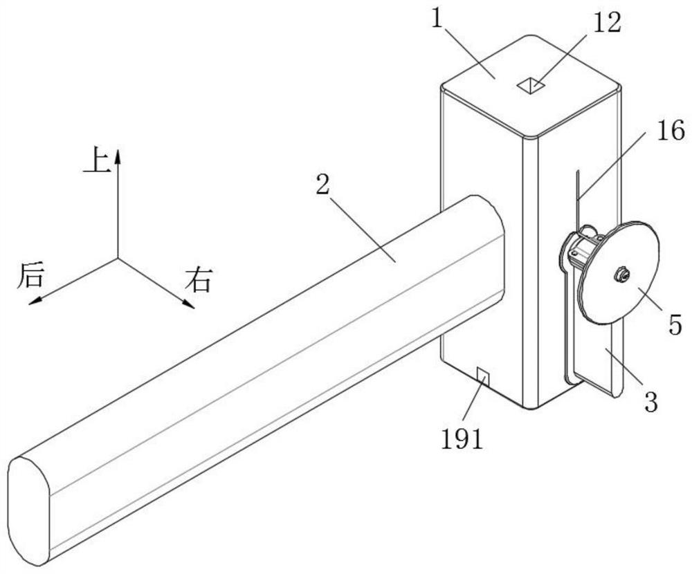
[0050] It should be noted that if figure 1 and Figure 8 As shown, the top of the cylindrical portion 32 is provided with a nail loading hole 321, so that nails can be loaded into the nail box 3 from the nail loading hole 321. A sealing cover 33 is detachably arranged on the nailing opening 321 . As a specific embodiment, first lugs 322 are respectively provided on both sides of the nailing opening 321, a plurality of position-limiting holes 3221 are provided on the first lugs 322, and the sealing cover 33 is provided with The second ear plate 331 corresponding to the first ear plate 322 is provided with a fixed plug 3311 corresponding to the limiting hole 3221 on the second ear plate 331 . The sealing cover 33 seals the nail binding opening 321 to prevent the nails inside the nail box from leaking out of the nail binding opening 321 when the hammer head 1 is used to bind nails.
[0051] As a specific implementation, such as Figure 6-8 As shown, the auger circle 4 is prov...
PUM
 Abstract
Description
Claims
Application Information
 - Generate Ideas
- Intellectual Property
- Life Sciences
- Materials
- Tech Scout
- Unparalleled Data Quality
- Higher Quality Content
- 60% Fewer Hallucinations
Browse by: Latest US Patents, China's latest patents, Technical Efficacy Thesaurus, Application Domain, Technology Topic, Popular Technical Reports.
© 2025 PatSnap. All rights reserved.Legal|Privacy policy|Modern Slavery Act Transparency Statement|Sitemap|About US| Contact US: help@patsnap.com