Brake device and electrically driven brake cylinder

A brake device and brake cylinder technology, applied in the field of railway wagons, can solve problems such as poor braking force output effect, achieve the effect of ensuring the rotation effect and improving the braking effect

Pending Publication Date: 2022-04-15
SHENHUA RAIL & FREIGHT WAGONS TRANSPORT +1
View PDF6 Cites 0 Cited by
  • Summary
  • Abstract
  • Description
  • Claims
  • Application Information

AI Technical Summary

Problems solved by technology

[0003] Based on this, it is necessary to provide a braking device and an electric drive brake cylinder for the problem of poor braking force output effect of the transmission brake cylinder.

Method used


Image

  • Brake device and electrically driven brake cylinder
  • Brake device and electrically driven brake cylinder
  • Brake device and electrically driven brake cylinder

Examples


Embodiment Construction

[0020] In order to make the above objects, features and advantages of the present invention more comprehensible, specific implementations of the present invention will be described in detail below in conjunction with the accompanying drawings. In the following description, numerous specific details are set forth in order to provide a thorough understanding of the present invention. However, the present invention can be implemented in many other ways different from those described here, and those skilled in the art can make similar improvements without departing from the connotation of the present invention, so the present invention is not limited by the specific embodiments disclosed below.

[0021] In describing the present invention, it should be understood that the terms "center", "longitudinal", "transverse", "length", "width", "thickness", "upper", "lower", "front", " Back", "Left", "Right", "Vertical", "Horizontal", "Top", "Bottom", "Inner", "Outer", "Clockwise", "Counte...


PUM


Abstract

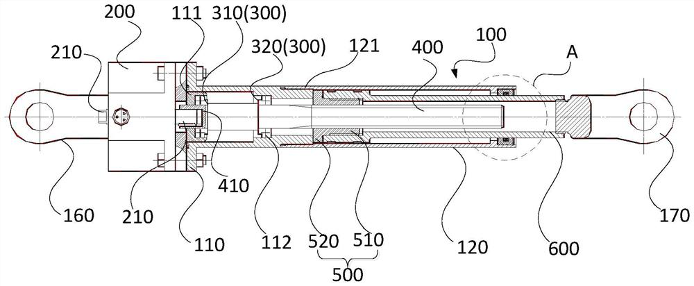
The invention relates to a brake device and an electrically driven brake cylinder. The electrically-driven brake cylinder comprises an installation cylinder body, a driving part, a bearing assembly, a threaded rod, a threaded transmission part and a telescopic part, the installation cylinder body is used for being installed and matched with one brake rod of a brake device, the installation cylinder body is provided with an assembly cavity, and the bearing assembly, the threaded rod and the threaded transmission part are all located in the assembly cavity; the output end of the driving part is inserted into the assembling cavity and is in installation fit with one end of the threaded rod, the threaded rod is sleeved with the bearing assembly, the bearing assembly is used for being in rotating fit with the threaded rod, and the threaded transmission part is in transmission fit with the threaded rod; one end of the telescopic piece abuts against the threaded transmission piece in a transmission mode, and the other end of the telescopic piece stretches out of the assembly cavity and is used for being installed and matched with the other brake rod of the brake device.

Description

technical field [0001] The invention relates to the technical field of railway wagons, in particular to a brake device and an electric drive brake cylinder. Background technique [0002] When the railway freight car is braking, the brake cylinder applies a braking force to the brake rod, thereby driving the brake shoe to collide with the wheel to achieve braking. The traditional brake cylinder drives the screw rod, telescopic rod and other components in turn through the drive motor for transmission. However, the traditional brake cylinder has a poor braking force output effect due to its own structural limitations when applying the braking force. Contents of the invention [0003] Based on this, it is necessary to provide a braking device and an electrically driven brake cylinder to solve the problem of poor braking force output effect of the transmission brake cylinder. [0004] An electric drive brake cylinder. The electric drive brake cylinder includes: a mounting cyl...

Claims


Application Information

Patent Timeline
Patent Type & Authority Applications(China)
IPC IPC(8): B60T13/74
Inventor 王喆波王蒙丁颖王洪昆王文刚边志宏王萌焦杨马瑞锋徐建喜张国彪曾德凉刘凤伟姜瑞金涂智文周乐
Owner SHENHUA RAIL & FREIGHT WAGONS TRANSPORT
Why Eureka
Try Eureka