Machine room air conditioning system control method and machine room air conditioning system

A technology of computer room air conditioning and control method, applied in mechanical equipment, cooling/ventilation/heating renovation, etc., can solve the problem of ineffective cooling in hotspot areas, and achieve the effect of solving ineffective cooling and eliminating local hotspots

Active Publication Date: 2022-04-15
QINGDAO HAIER AIR CONDITIONING ELECTRONICS CO LTD +2
View PDF11 Cites 2 Cited by
  • Summary
  • Abstract
  • Description
  • Claims
  • Application Information

AI Technical Summary

Problems solved by technology

[0005] The invention provides a control method for an air-conditioning system in a computer room, which solves the problem that the hot spot area in the computer room cannot effectively cool down

Method used


Image

  • Machine room air conditioning system control method and machine room air conditioning system
  • Machine room air conditioning system control method and machine room air conditioning system

Examples


Embodiment 1

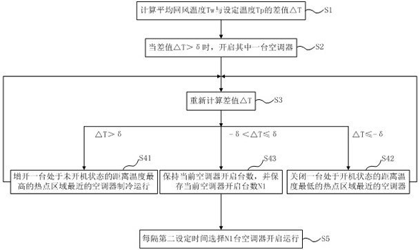
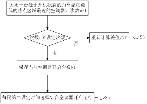
[0048] The computer room air conditioning system control method of this embodiment mainly includes the following steps, see figure 1 shown.

[0049] After the computer room air conditioning system is powered on, perform the following steps.

[0050] Step S1: Calculate the difference ΔT between the average return air temperature Tw and the set temperature Tp; ΔT=Tw-Tp.

[0051] in, T i is the temperature at the indoor return air outlet of the i-th air conditioner, i=1,2,3,...,N.

[0052] T1 is the temperature at the indoor return air outlet of the first air conditioner;

[0053] T2 is the temperature at the indoor return air outlet of the second air conditioner;

[0054] ...

[0055] TN is the temperature at the indoor return air outlet of the Nth air conditioner.

[0056]Tw=(T1+T2+T3+...+TN) / N.

[0057] The set temperature Tp is the target temperature, which is set by the host.

[0058] Firstly, the temperature at the indoor air return port of each air conditioner is...

Embodiment 2

[0117] Based on the design of the control method of the computer room air-conditioning system in the first embodiment, the second embodiment proposes a computer room air-conditioning system, which adopts the control method of the computer room air-conditioning system in the first embodiment.

[0118] Specifically, the master receives the information transmitted by each temperature sensor and each slave, executes the above computer room air conditioning system control method, and controls the operation of each slave to reduce the temperature of the computer room and prevent local overheating.

[0119] The computer room air-conditioning system of this embodiment, by adopting the above-mentioned control method, quickly responds to the temperature in the computer room, eliminates local hot spots in the computer room, quickly realizes temperature balance in the computer room, and solves the problem that the hot spots in the computer room cannot be effectively cooled.


PUM


Abstract

The invention discloses a machine room air conditioning system control method and a machine room air conditioning system. The method comprises the steps that the difference value T between the average return air temperature Tw and the set temperature Tp is calculated; when the difference value T is larger than delta, an air conditioner which is in a non-starting state and is closest to the hot spot area with the highest temperature is additionally started for refrigeration operation; when the difference value T is smaller than or equal to-delta, the air conditioner which is in the starting state and is closest to the hot spot area with the lowest temperature is turned off; when delta is larger than-delta and smaller than or equal to delta, the number of the current started air conditioners is kept, and the number N1 of the current started air conditioners is stored; n1 air conditioners are selected to be started every second set time; according to the machine room air conditioning system control method and the machine room air conditioning system, the temperature in the machine room is quickly responded, local hot spots in the machine room are eliminated, temperature balance of the machine room is quickly achieved, and the problem that hot spot areas in the machine room cannot be effectively cooled is solved.

Description

technical field [0001] The invention belongs to the technical field of air conditioning, and in particular relates to a control method for an air conditioning system in a computer room and the air conditioning system in a computer room. Background technique [0002] There are many electronic devices placed in a large data center, and local hot spots are prone to occur. [0003] The air conditioner in the computer room is used to cool down the equipment in the computer room. At present, the temperature is set only through the fixed temperature sensor of the air conditioner itself, and the temperature sensor of the air conditioner cannot effectively identify the hot spots in the local key locations in the entire computer room. In actual use, there is a problem that some overheated areas cannot be effectively cooled. [0004] In addition, the blind air supply has no directivity, resulting in uneven temperature in the entire computer room, which is prone to energy waste. Cont...

Claims


Application Information

Patent Timeline
Patent Type & Authority Applications(China)
IPC IPC(8): F24F11/64F24F11/65F24F11/79H05K7/20
Inventor 姜荣伟杨公增马韵华
Owner QINGDAO HAIER AIR CONDITIONING ELECTRONICS CO LTD
Why Eureka
Try Eureka