
Soil environment monitoring equipment based on new energy

An environmental monitoring and soil monitoring technology, applied in the field of soil environmental monitoring, can solve problems such as poor stability, inability to adjust the angle, and damage to the soil environment monitoring device when it is dumped, and achieve the effect of preventing dumping and improving absorption

Pending Publication Date: 2022-04-15
浙江君正环境科技有限公司
View PDF11 Cites 1 Cited by
  • Summary
  • Abstract
  • Description
  • Claims
  • Application Information

AI Technical Summary

Problems solved by technology

[0006] The present invention provides a soil environment monitoring device based on new energy, one of which is to facilitate the adjustment of the angle of the solar panel, improve the absorption of solar energy by the solar panel, and solve the problem that the angle of the solar panel is fixed and cannot be adjusted. The problem of adjusting its angle; another purpose is to solve the problem that the soil environment monitoring equipment is poor in stability, and the soil environment monitoring device is often dumped and damaged due to human rubbing, so as to achieve good stability of the soil environment monitoring equipment , to prevent the soil environment monitoring equipment from being damaged due to the unintentional rubbing of the monitor

Method used


Image

  • Soil environment monitoring equipment based on new energy
  • Soil environment monitoring equipment based on new energy
  • Soil environment monitoring equipment based on new energy

Examples


Embodiment 1

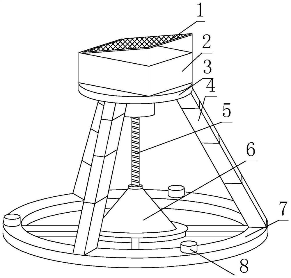
[0036] Such as Figure 1-6As shown, the present invention provides a new energy-based soil environment monitoring equipment, including a power supply device 1, the bottom of the power supply device 1 is provided with a soil monitoring collection and processing box 2, and the bottom of the soil monitoring collection and processing box 2 is fixedly installed with an upper fixed Disc 3, monitor 5 is fixedly installed at the shaft center of the bottom of the upper fixed disc 3, the edge of the lower surface of the upper fixed disc 3 is rotatably connected with a telescopic support rod 4, and the other end of the telescopic support rod 4 is rotatably connected with a lower The support disc 7, the outer wall of the bottom of the monitor 5 is threadedly connected with a fixed frame 6, the outer wall of the bottom of the fixed frame 6 is fixedly installed with the inner wall of the lower support disc 7 through a pole, and the upper surface of the lower support disc 7 is provided with a...

Embodiment 2

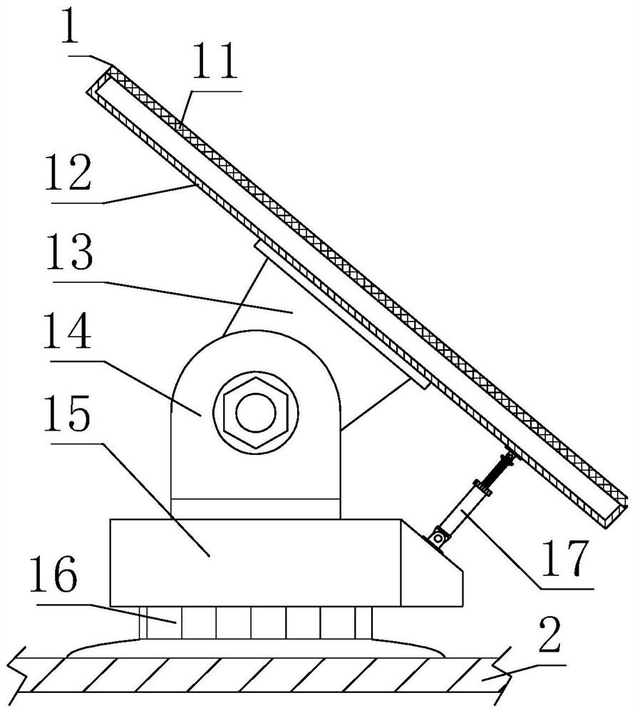
[0039] Such as Figure 1-6 Shown, on the basis of embodiment 1, the present invention provides a kind of technical scheme: preferably, power supply device 1 comprises solar panel rotating seat 16, and the bottom of solar panel rotating seat 16 is fixed with the upper surface of soil monitoring collecting and processing box 2 Installation, the upper surface of the solar panel rotating seat 16 is fixedly installed with a solar panel fixed base 15, and the top of the solar panel fixed base 15 is fixedly installed with a solar panel rotating support block 14, and the axis of the solar panel rotating support block 14 is rotatably connected with a solar panel. Plate support rotating block 13, solar panel support 12 is fixedly installed on the upper right of solar panel support rotating block 13, solar panel 11 is fixedly installed on the upper right of solar panel support 12, and the top of solar panel fixed base 15 right side is provided with solar panel Angle adjustment support 17...

Embodiment 3

[0042] Such as Figure 1-6 As shown, on the basis of Embodiment 1, the present invention provides a technical solution: preferably, the monitor 5 includes a casing 51, the upper surface of the casing 51 is fixedly installed at the axis of the bottom of the upper fixed disc 3, and the casing 51 A motor 52 is fixedly installed on the top of the inner chamber, a monitor probe rod fixing block 53 is fixedly installed on the rotating shaft at the bottom of the motor 52, and a monitor probe rod 54 is fixedly installed on the bottom of the monitor probe rod fixing block 53, and a monitor probe rod 54 The bottom of the monitor probe rod 54 is fixedly equipped with a drill bit 59, and the bottom of the outer wall of the monitor probe rod 54 is fixedly equipped with a soil monitoring probe 58. The outer wall of the monitor probe rod 54 and the bottom of the inner cavity of the cabinet 51 are movably socketed with a receiving probe bracket 55, and the receiving probe The inner wall of th...


PUM


Abstract

The invention discloses soil environment monitoring equipment based on new energy, and relates to the technical field of soil environment monitoring, the soil environment monitoring equipment comprises a power supply device, the bottom of the power supply device is provided with a soil monitoring, collecting and processing box, and the bottom of the soil monitoring, collecting and processing box is fixedly provided with an upper fixed disc; a monitor is fixedly installed at the axis of the bottom of the upper fixing disc, and a telescopic support rod is rotationally connected to the edge of the lower surface of the upper fixing disc. Through the effect of the solar panel, electricity is provided for the soil environment monitoring equipment, the soil environment monitoring equipment can monitor soil conveniently, an adjusting rotating ring is rotated, and an adjusting threaded rod is stretched out and drawn back, so that the inclination angle of the solar panel is adjusted, and absorption of the solar panel to solar energy is improved; sufficient power is provided for the soil environment monitoring equipment, and the situation that the soil environment monitoring equipment cannot work normally due to insufficient power, and consequently the monitoring efficiency of the soil environment is affected is prevented.

Description

technical field [0001] The invention relates to the technical field of soil environment monitoring, in particular to a new energy-based soil environment monitoring device. Background technique [0002] Soil is the main body of nature composed of layers of mineral components with different thicknesses. It is a mixed part of minerals and organic matter. It exists in solid, gas and liquid states. The loose soil particles are combined to form a void filled with gaps. form of soil. [0003] There are following problems at prior art: [0004] 1. In the existing soil environment monitoring equipment, the angle of the solar panel is fixed, and the angle cannot be adjusted, which reduces the utilization rate of solar energy by the solar panel, and often occurs that the solar panel does not provide enough power for the soil environment monitoring device. Affect the monitoring of the soil environment; [0005] 2. The stability of the existing soil environment monitoring equipment is...

Claims


Application Information

Patent Timeline
Patent Type & Authority Applications(China)
IPC IPC(8): G01N33/24H02S20/30
CPCY02E10/50
Inventor 廖玲玲刘文彪刘育玮
Owner 浙江君正环境科技有限公司
Learn More