
Multi-layer soil monitor

A soil monitoring and soil layer technology, applied in soil material testing, material inspection products, etc., can solve the problems of difficulty, increase time cost, production cost, and high maintenance cost, and achieve the purpose of improving service life, shortening testing period, and reducing maintenance. cost effect

Active Publication Date: 2022-04-15
广州海睿智能科技股份有限公司
View PDF10 Cites 0 Cited by
  • Summary
  • Abstract
  • Description
  • Claims
  • Application Information

AI Technical Summary

Problems solved by technology

Once the sensor ages, it will affect the accuracy of the soil monitoring results, so the sensor must be replaced during maintenance
However, because most of the existing monitors have an integrated structure, it is necessary to disassemble the soil monitor as a whole when replacing the sensor. The maintenance cost is high, difficult and inconvenient.
In addition, the number of layers of the existing multi-layer soil monitors is generally fixed, so the existing monitors cannot adapt to work according to the number of soil layers, and it is necessary to re-use the Multi-layer soil monitors with other layers greatly increase the cost
If there is no monitor that matches the layers of the soil to be measured, another custom-made equipment is required, which greatly increases the time cost and production cost

Method used


Image

  • Multi-layer soil monitor
  • Multi-layer soil monitor
  • Multi-layer soil monitor

Examples


Embodiment Construction

[0034] In order to enable those skilled in the art to better understand the solutions of the present application, the following will clearly and completely describe the technical solutions in the embodiments of the present application with reference to the drawings in the embodiments of the present application. Apparently, the described implementations are only some of the implementations of this application, not all of them. Based on the implementation manners in this application, all other implementation manners obtained by those skilled in the art without creative efforts shall fall within the scope of protection of this application.

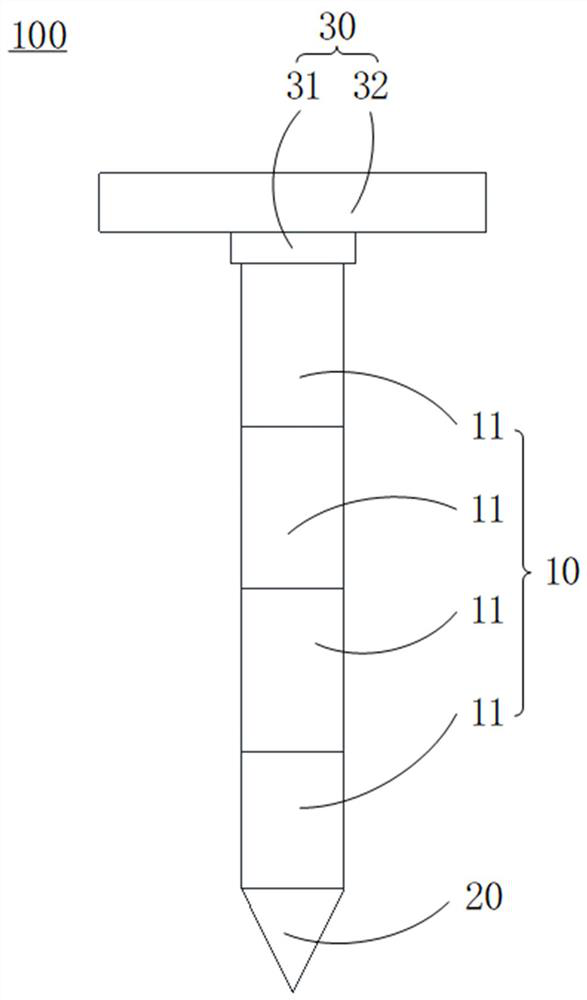
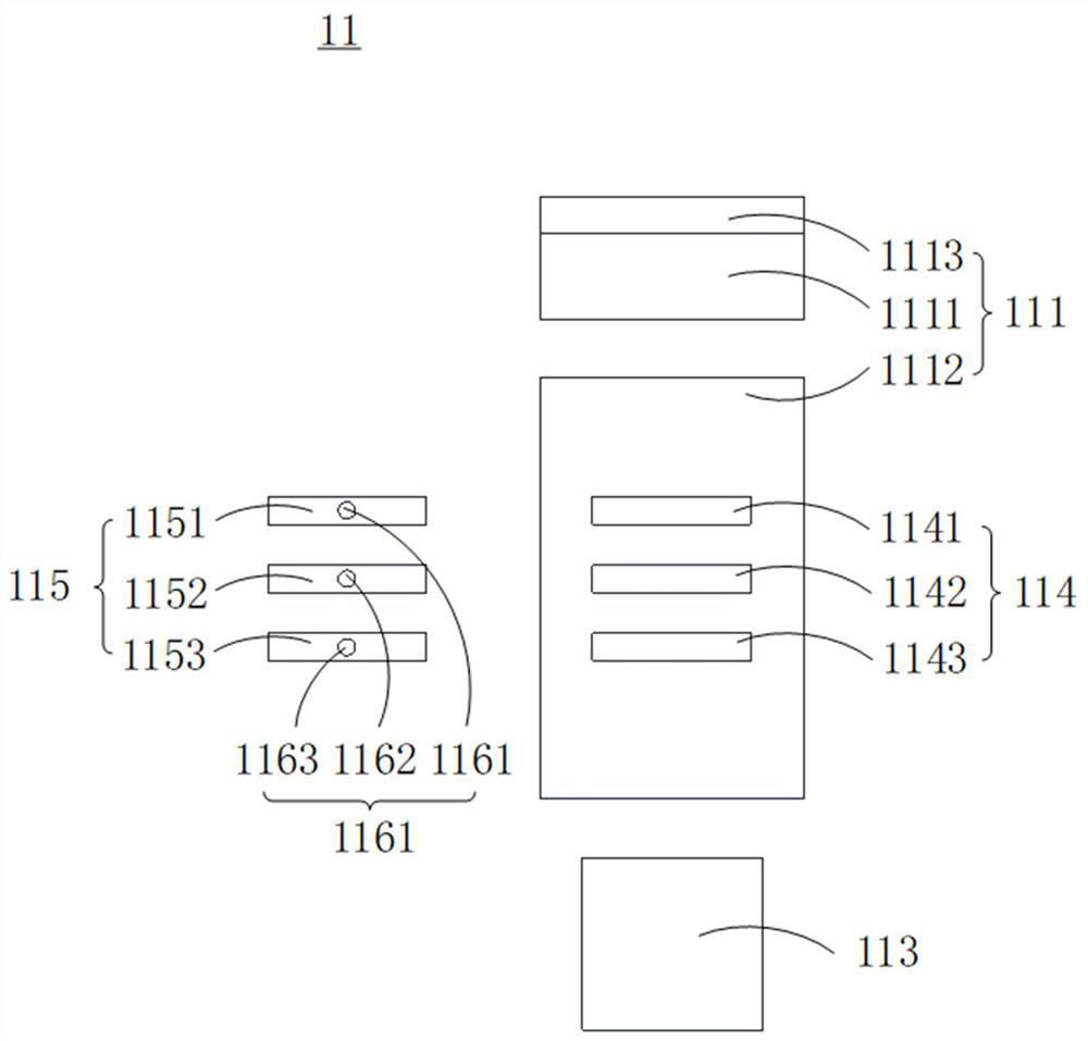
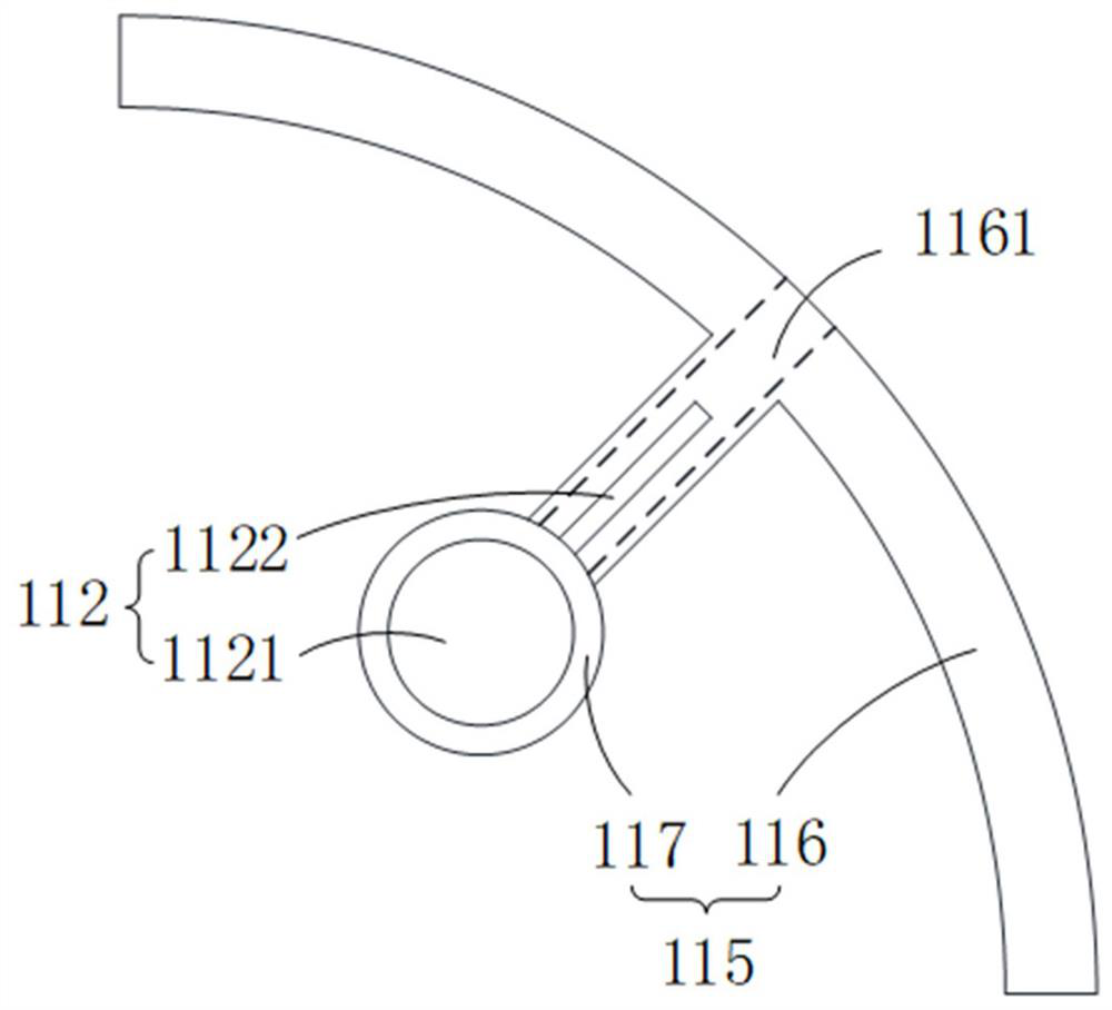
[0035] Please also refer to Figure 1 to Figure 4 , the embodiment of the present application provides a multi-layer soil monitor 100, which is suitable for measuring soil layers with at least two layers, including a working part 10, the working part 10 has opposite first ends and second ends, and the working part 10 includes at least two A ...


PUM


Abstract

The invention provides a multi-layer soil monitor which comprises a working part, the working part is provided with a first end and a second end which are opposite, the working part comprises working units, each working unit is provided with a head end and a tail end, and the head end of one working unit is detachably connected with the tail end of the adjacent working unit. Each working unit comprises a shell, a measuring device and a circuit board, the shell is provided with a first connecting part and a second connecting part, the first connecting part is located at the head end of the working unit, the second connecting part is located at the tail end of the working unit, and the first connecting part is used for detachably connecting the second connecting part of the adjacent working unit; a containing cavity is defined by the shell. The measuring device is arranged on the shell and is used for detecting soil parameters of the corresponding soil layer and generating soil parameter signals; the circuit board is arranged in the containing cavity, the measuring device is electrically connected with the circuit board, and the circuit board is used for controlling the measuring device to selectively work or stop working and receiving soil parameter signals generated by the measuring device.

Description

technical field [0001] The application relates to the field of soil monitoring equipment, in particular to a multi-layer soil monitoring instrument. Background technique [0002] Existing multi-layer soil monitors generally have a one-piece structure with a large volume, and the multi-layer soil monitors mainly rely on sensors that need to be in contact with the soil and sensors installed inside the monitor to monitor the soil, so the sensor hardware of the monitor is aging phenomenon is very common. Once the sensor is aging, it will affect the accuracy of soil monitoring results, so the sensor must be replaced during maintenance. However, because most of the existing monitors have an integrated structure, the soil monitor needs to be dismantled as a whole when replacing the sensor, and the maintenance cost is high, difficult and inconvenient. In addition, the number of layers of the existing multi-layer soil monitors is generally fixed, so the existing monitors cannot ada...

Claims


Application Information

Patent Timeline
IPC IPC(8): G01N33/24
Inventor 叶云姜晟冉耀虎江晓发刘遵亮黄伟波曾伟乐温涛
Owner 广州海睿智能科技股份有限公司
Learn More