
Radio-frequency mixed signal integrated circuit test system and test method

An integrated circuit and radio frequency hybrid technology, which is applied in the field of radio frequency mixed signal integrated circuit test system and test, can solve the problems of unsuitable radio frequency integrated circuit test, large area of ​​test interface board, long production cycle, etc., so as to improve test efficiency and shorten The effect of reducing processing cycle and production cost

Active Publication Date: 2019-05-03
西安太乙电子有限公司
View PDF5 Cites 11 Cited by
  • Summary
  • Abstract
  • Description
  • Claims
  • Application Information

AI Technical Summary

Problems solved by technology

This method has the obvious disadvantages of large test interface board area, high price, and long production cycle, especially when there are many types of integrated circuit tests, the price and time cost of making test interface boards are very obvious.
[0008] In addition, since the operating frequency of most integrated circuits is below 0.1GHz, the signal wavelength is much larger than the size of the circuit board. At this time, the test system can be regarded as a lumped circuit system, and the loss on the signal line between modules or components can be Neglected, the circuit board signal lines connecting ATE and integrated circuits only serve as electrical connections
When it comes to the frequency band above 0.1GHz, that is, the main working frequency band of radio frequency integrated circuits, as the signal wavelength gradually decreases, the circuit board signal lines that only serve as electrical connections in traditional integrated circuit testing have serious problems in high frequency testing. The phenomenon of reflection, crosstalk, noise and electromagnetic interference, the traditional ATE test method cannot be applied to the test of radio frequency integrated circuits due to the sharp increase in the error of the test interface board caused by the increase in frequency

Method used


Image

  • Radio-frequency mixed signal integrated circuit test system and test method
  • Radio-frequency mixed signal integrated circuit test system and test method
  • Radio-frequency mixed signal integrated circuit test system and test method

Examples


Embodiment Construction

[0056] A radio frequency signal integrated circuit testing system of the present invention will be further described below in conjunction with the accompanying drawings.

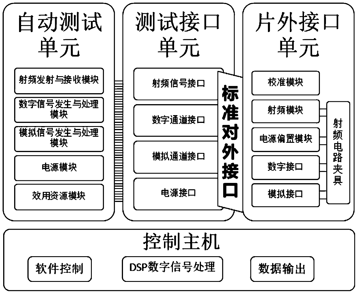
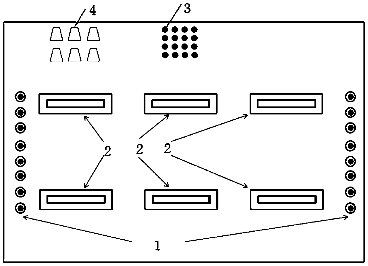
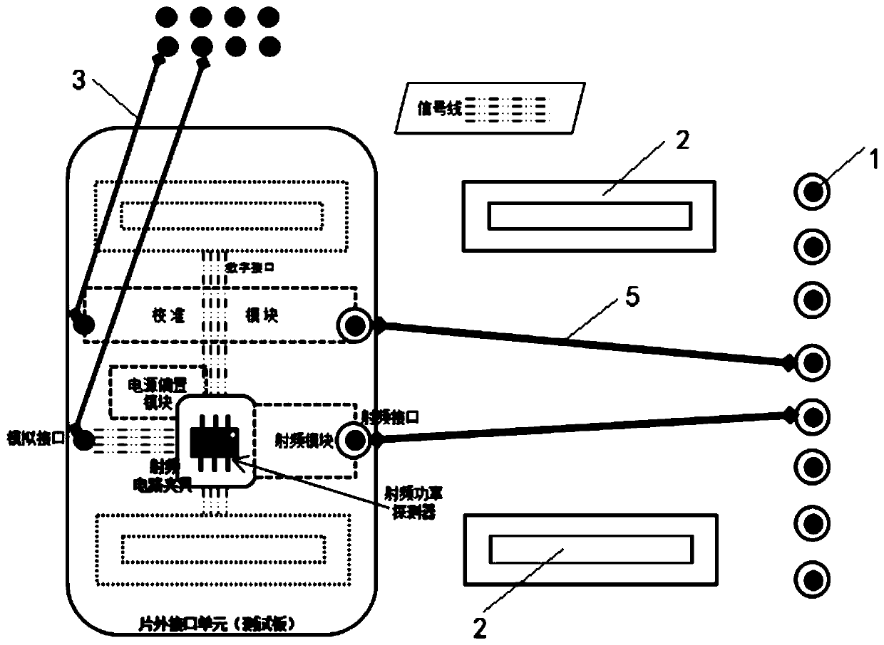
[0057] The solution adopted by the present invention is: the radio frequency mixed-signal integrated circuit test system is composed of an automatic test unit, a test interface unit, an off-chip interface unit, and a control host, and the control host software controls the automatic test unit action and outputs a test report; the automatic test unit Generate excitation signals and expected signals, capture response signals, and return comparison results to the control host; the test interface unit is connected to the automatic test unit and integrates various types of signal interfaces into a standard external interface with low density, simple docking process, and distinguishing signal types, bidirectional transmission Stimulus and response signals; the calibration module of the off-chip interface unit reali...


PUM


Abstract

The invention discloses a radio-frequency mixed signal integrated circuit test system and test method. An automatic test unit, a test interface unit, an off-chip interface unit and a control host formthe test system. The control host software controls the automatic test unit to take action and a test report is outputted; the automatic test unit generates an excitation signal and a desired signal,captures a response signal, and returns a comparison result to the control host; the test interface unit connects the automatic test unit and integrates all types of signal interfaces into a low-density simple-docking-process standard external interface capable of distinguishing signal types so as to transmit the excitation and response signals in a bidirectional manner; and the calibration module of the off-chip interface unit is used for realizing radio frequency error separation of the test interface unit and the off-chip interface unit and a to-be-tested circuit is connected to the standard external interface through the off-chip interface unit to input an excitation signal and output a response signal. Therefore, universal high-performance high-efficiency and low-cost integrated testing of the radio-frequency mixed signal integrated circuit from the 0.1GHz to 12GHz is realized.

Description

technical field [0001] The invention relates to a test system and a test method, which are suitable for testing radio frequency integrated circuits, especially suitable for testing radio frequency mixed signal integrated circuits. Background technique [0002] Traditional radio frequency integrated circuits use single or multiple instruments, such as radio frequency network analyzers, radio frequency signal sources, radio frequency power meters, spectrum signal analyzers, programmable control power supplies, etc., to build a combined test system for testing. [0003] According to the different types of radio frequency integrated circuits to be tested, different combinations of instruments and meters are selected to build a test system for this type of radio frequency integrated circuits. For passive RF circuits, such as RF filters, use a single network analyzer, or a combination of RF signal source and RF power meter; for active fixed-frequency RF circuits, such as RF amplif...

Claims


Application Information

Patent Timeline
IPC IPC(8): G01R31/28
Inventor 夏勇权马宝锋
Owner 西安太乙电子有限公司
Learn More