Lens dirt identification method and device, computer equipment and storage medium

A recognition method and dirt technology, applied in computing, image data processing, instruments, etc., can solve the problems of misjudgment or missed judgment of lens dirt, vignetting around the lens, etc., and achieve accurate and effective results

Pending Publication Date: 2022-04-15
AAC OPTICS(NANNING)TECH LTD
View PDF0 Cites 2 Cited by
  • Summary
  • Abstract
  • Description
  • Claims
  • Application Information

AI Technical Summary

Problems solved by technology

[0003] The main purpose of the present invention is to provide a lens dirty recognition method, device, computer equipment and storage medium, which can solve the problem of vignetting around the lens in the prior art, resulting in misjudgment or missed judgment of lens dirty

Method used


Image

  • Lens dirt identification method and device, computer equipment and storage medium
  • Lens dirt identification method and device, computer equipment and storage medium
  • Lens dirt identification method and device, computer equipment and storage medium

Examples


Embodiment Construction

[0052] The following will clearly and completely describe the technical solutions in the embodiments of the present invention with reference to the accompanying drawings in the embodiments of the present invention. Obviously, the described embodiments are only some, not all, embodiments of the present invention. Based on the embodiments of the present invention, all other embodiments obtained by persons of ordinary skill in the art without creative efforts fall within the protection scope of the present invention.

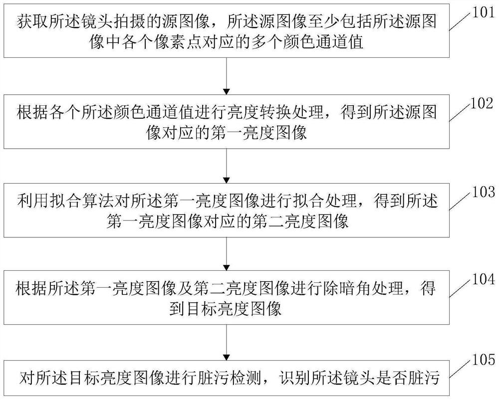
[0053] refer to figure 1 , figure 1 It is a flow chart of a method for identifying lens contamination in an embodiment of the present invention. The method for identifying lens contamination specifically includes the following steps:

[0054] 101. Acquire a source image captured by the lens, where the source image at least includes a plurality of color channel values ​​corresponding to each pixel in the source image;

[0055]In this embodiment, the image captured...


PUM


Abstract

The embodiment of the invention discloses a lens smudginess identification method and device, computer equipment and a storage medium, and the method comprises the steps: obtaining a source image shot by a lens, the source image at least comprising a plurality of color channel values corresponding to each pixel point in the source image; performing brightness conversion processing according to each color channel value to obtain a first brightness image corresponding to the source image; performing fitting processing on the first brightness image by using a fitting algorithm to obtain a second brightness image corresponding to the first brightness image; performing dark corner removal processing according to the first brightness image and the second brightness image to obtain a target brightness image; and carrying out smudginess detection on the target brightness image, and identifying whether the lens is smudginess. According to the method, the target brightness image without the vignetting is obtained by using the first brightness image subjected to brightness conversion and the second brightness image subjected to fitting, and whether the lens is dirty or not is identified on the premise of removing the vignetting, so that the result is more accurate and effective.

Description

technical field [0001] The invention relates to the technical field of camera production, in particular to a method, device, computer equipment and storage medium for recognizing lens dirt. Background technique [0002] In the actual production process of the camera module, because the workshop is not an ideal dust-free environment, the imaging sensor and filter are in contact with the air before the lens is installed, and foreign matter such as dust and dander in the air is easy to adhere to the imaging sensor or filter. On the light sheet, the final camera module will be dirty during imaging, which will seriously affect the image quality. The current detection method is to compare the brightness of the current area with the surrounding area. When the contrast is greater than the set threshold, it is considered dirty. This method is easily affected by shading. Shading refers to the vignetting of the lens. Due to the problem of the mounting process, the tilt of the lens or ...

Claims


Application Information

Patent Timeline
Patent Type & Authority Applications(China)
IPC IPC(8): G06T7/90G06T7/155G06T7/11G06T7/00G06T5/00
Inventor 叶威铅
Owner AAC OPTICS(NANNING)TECH LTD
Why Eureka
Try Eureka