Medical postoperative back wound nursing device

A technology for wound care and medical use, which is applied to other medical devices, drug devices, drug devices, etc. It can solve the problems of clothing pollution, small spraying range, and easy liquid medicine sticking to the body, so as to facilitate storage and speed up the process. absorption effect

Pending Publication Date: 2022-04-19
韩明洋
View PDF1 Cites 0 Cited by
  • Summary
  • Abstract
  • Description
  • Claims
  • Application Information

AI Technical Summary

Problems solved by technology

[0005] In order to overcome the shortcomings of the existing spraying smearing device, the spraying range is small, and the excess liquid medicine is easy to stick on the body, thereby causing clothing pollution. Medical postoperative back wound care device capable of collecting excess medical solution

Method used


Image

  • Medical postoperative back wound nursing device
  • Medical postoperative back wound nursing device
  • Medical postoperative back wound nursing device

Examples


Embodiment 1

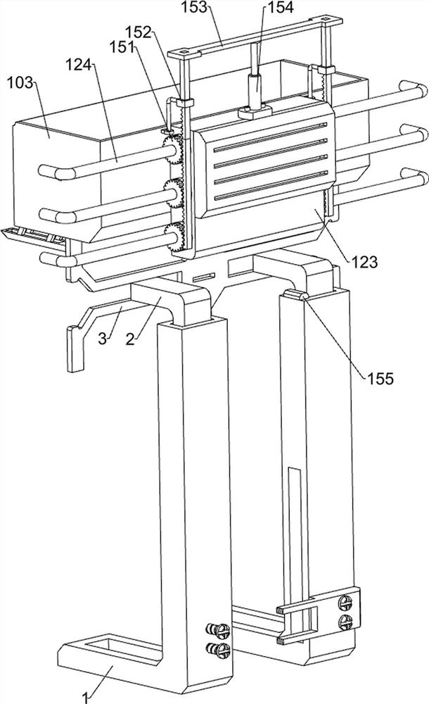
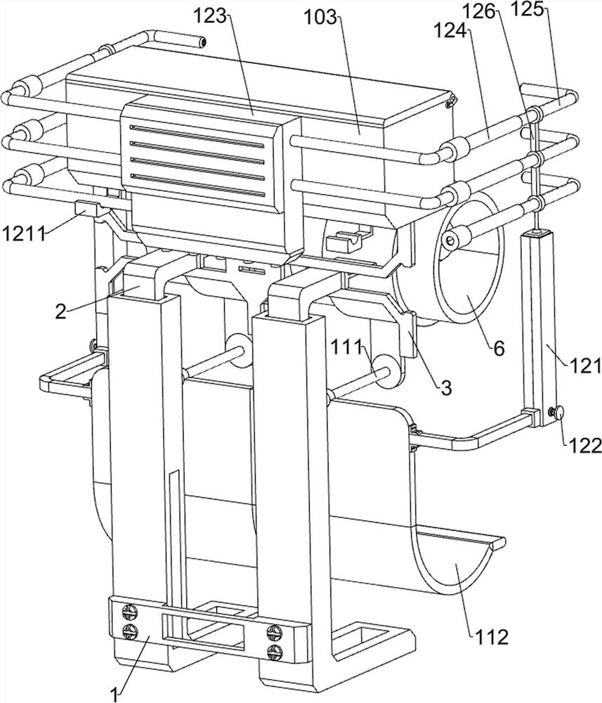
[0041] see Figure 1-Figure 8 As shown, a postoperative back wound care device for medical use includes a mounting base 1, a moving rod 2, a mounting frame 3, a fixed plate 31, a control box 4, a handle 5, a mounting cylinder 6, a rotating cylinder 7, a nozzle 8, The rotating assembly 10 and the collecting assembly 11, the left and right symmetrical slides in the mounting seat 1 are provided with a moving rod 2, a mounting frame 3 is arranged between the upper parts of the two moving rods 2, and a fixed plate 31 is arranged on the left and right sides of the mounting frame 3. The left and right sides of the frame 3 are provided with handles 5, the handles 5 are located outside the fixed disks 31, and a rotating cylinder 7 is arranged between the two fixed disks 31, and a mounting cylinder 6 is arranged outside the rotating cylinder 7, and the mounting cylinder 6 and the mounting frame 3 Rotary connection, a ring of nozzles 8 is arranged between the left and right sides of the ...

Embodiment 2

[0044] see Figure 5 , Image 6 , Figure 17 with Figure 18 As shown, on the basis of Embodiment 1, the rotating assembly 10 includes a large gear 101, a first connecting pipe 102, a water storage tank 103, a first driving motor 104, a first distance sensor 105 and a spur gear 106, and the rotating cylinder 7 The left and right sides are all key-connected with a large gear 101, the large gear 101 is located on the outside of the nozzle 8, the top of the installation frame 3 is welded with a water storage tank 103, the water storage tank 103 is used to store the liquid medicine, and the top of the water storage tank 103 is rotatably provided with a tank cover, which stores The left and right sides of the water tank 103 are provided with a first connecting pipe 102, the rotating cylinder 7 is connected to the first connecting pipe 102 in a rotational manner, and communicated, and the middle part of the front side of the mounting frame 3 is provided with a first driving motor ...

Embodiment 3

[0049] see Figure 9 , Figure 10 , Figure 11 , Figure 17 with Figure 18 As shown, on the basis of Embodiment 2, an air blowing assembly 12 is also included. The air blowing assembly 12 is used to accelerate the absorption of liquid medicine. The air blowing assembly 12 includes a guide frame 121, a winding wheel 122, a hot air blower 123, The second connecting pipe 124, the third connecting pipe 125, the connecting frame 126, the fixed block 127, the third distance sensor 128, the torsion spring 129, the stay cord 1210 and the limit block 1211, and the left and right sides of the collecting plate 112 are provided with guide frames 121, the lower parts of the two guide frames 121 are rotatably provided with winding wheels 122, the rear side of the water storage tank 103 is provided with a hot air blower 123, and the hot air blower 123 is used to generate hot air. The second connecting pipe 124, the third connecting pipe 125 is slidingly arranged in the front sides of th...


PUM


Abstract

The invention relates to a back wound nursing device, in particular to a medical postoperative back wound nursing device. The invention provides a medical postoperative back wound nursing device which is large in medicine spraying range and capable of collecting redundant medicine liquid. The medical postoperative back wound nursing device comprises a mounting base, and moving rods are arranged in the mounting base in a bilateral symmetry sliding mode; the mounting frame is arranged between the upper parts of the two moving rods; the fixing discs are arranged on the left side and the right side of the mounting frame; the handles are arranged on the left side and the right side of the mounting frame and located on the outer side of the fixing disc. An output shaft of a first driving motor rotates to drive a straight gear to rotate, so that a rotating cylinder rotates to drive a spray head to rotate, liquid medicine is sprayed to the back of the patient, and then medicine applying nursing on the back of the patient is achieved.

Description

technical field [0001] The invention relates to a back wound care device, in particular to a medical postoperative back wound care device. Background technique [0002] After surgery on the patient's back, medication needs to be administered to the wound. In order to allow the drug to be absorbed by the skin faster and allow the patient's wound to heal quickly, it is necessary to use a drug spraying device to spray the drug to the patient's wound. [0003] The patent authorization announcement number is CN112023202A, which discloses a medical spray application device and its use method. The spray application device specifically includes a base, and the top outer wall of the base is connected to the cartridge through a connection reset assembly. The outer wall of the bottom of the base is provided with a spraying assembly, the inside of the cartridge is provided with a sealing assembly, the outer wall of the top of the cartridge is provided with a holding and spraying assembl...

Claims


Application Information

Patent Timeline
Patent Type & Authority Applications(China)
IPC IPC(8): A61M35/00A61M37/00
CPCA61M35/20A61M37/00A61M2037/0007A61M2205/362A61M2205/33
Inventor 韩明洋
Owner 韩明洋
Why Eureka
Try Eureka