
a cutting device

A technology of ironing rollers and racks, applied in the field of cutting devices, which can solve the problems of difficult collection of cutting thread ends, achieve the effect of enhancing the leveling effect and solving the difficulty of collecting thread ends

Active Publication Date: 2020-05-12
清远市佳伦毯业织造有限公司
View PDF9 Cites 0 Cited by
  • Summary
  • Abstract
  • Description
  • Claims
  • Application Information

AI Technical Summary

Problems solved by technology

[0004] The present invention intends to provide a cutting device to solve the problem that the cutting wire ends generated during the cutting process are difficult to collect

Method used


Image

  • a cutting device
  • a cutting device

Examples


Embodiment Construction

[0017] The present invention will be described in further detail below by means of specific embodiments:

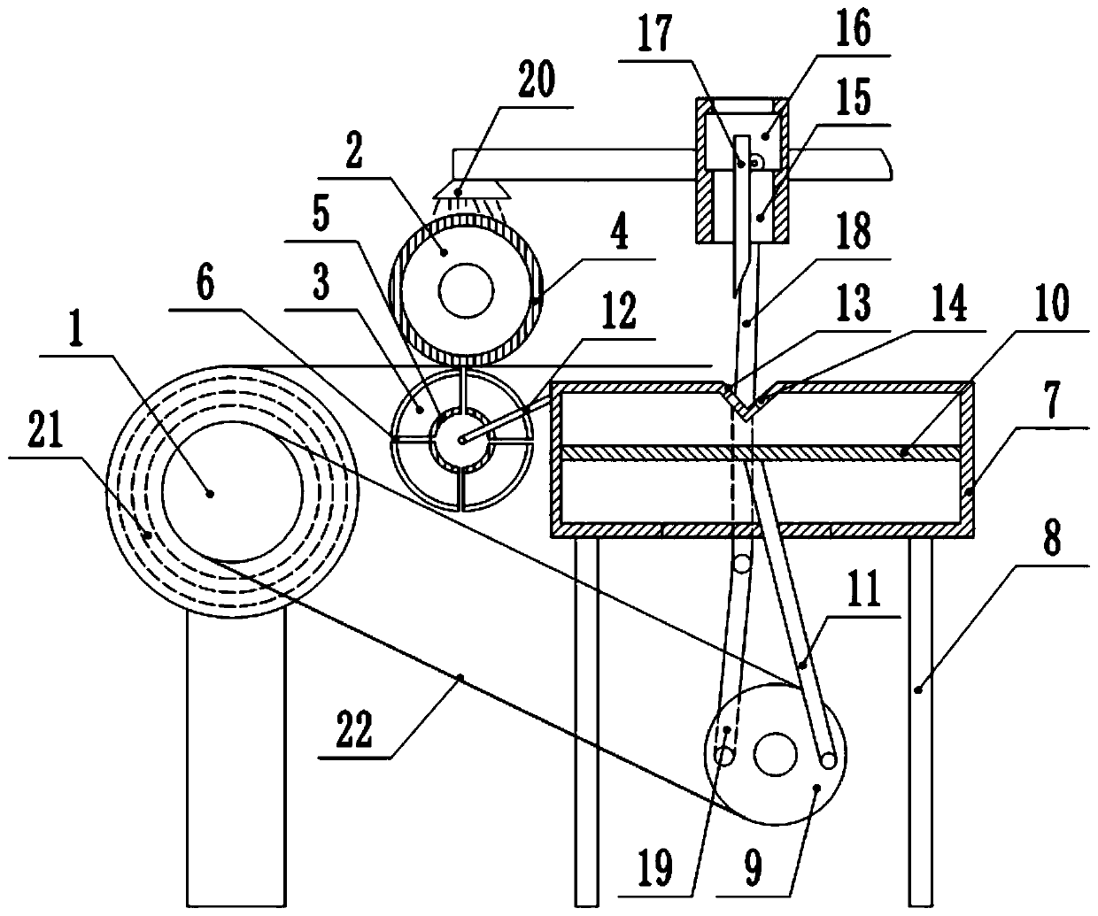
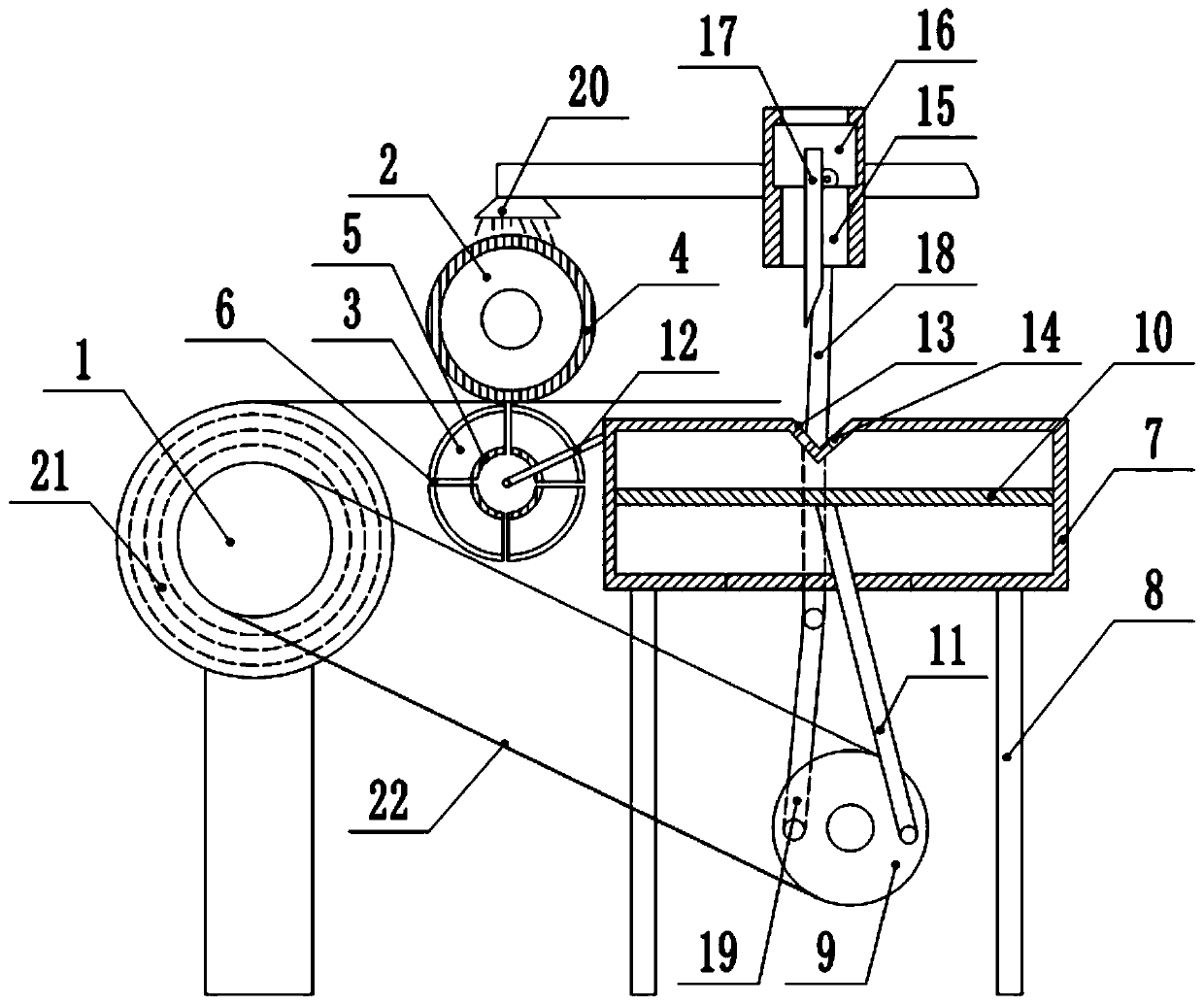
[0018] The reference signs in the drawings of the description include: rotating shaft 1, first ironing roller 2, second ironing roller 3, first heating layer 4, second heating layer 5, air outlet 6, operation box 7, support rod 8 , drive shaft 9, slide plate 10, push rod 11, air guide pipe 12, knife slot 13, suction port 14, chute 15, slider 16, cutting knife 17, first pull rod 18, second pull rod 19, nozzle 20, Cloth drum 21, conveyor belt 22.

[0019] The embodiment is basically as figure 1 Shown: a cutting device, including a frame and a rotating shaft 1, the rotating shaft 1 is rotatably connected to the frame, the rotating shaft 1 is provided with a buckle for clamping the cloth tube 21, and the frame is also provided with an ironing mechanism. The ironing mechanism comprises a first ironing roller 2 and a second ironing roller 3, the first ironing roller 2 and the...


PUM


Abstract

The invention relates to a cutting device which comprises a rack, a rotating shaft, a first ironing roll and a second ironing roll, wherein the first ironing roll and the second ironing roll are rotationally connected onto the rack; a first heating layer is arranged on the first ironing roll; the interior of the second ironing roll is hollow, and a second heating layer is arranged on the second ironing roll; an air inlet and an air outlet are formed in the second ironing roll; an operating box is arranged on one side of the second ironing roll; a driving shaft is arranged below the operating box; a sliding plate is connected in the operating box in a sliding manner; a push rod is hinged onto the sliding plate; the other end of the push rod is connected onto the driving shaft; an air-blowing port, a cutter groove and an air suction port are formed in the operating box; the air-blowing port is connected with a gas-guide tube; the other end of the gas-guide tube is communicated with the air inlet; the cutter groove is positioned in the upper surface of the operating box; the air suction port is positioned in the walls of the cutter groove; a chute is formed above the cutter groove; aslide block is connected in the chute in a sliding manner; a cutter is connected onto the slide block; a pull rod is hinged at the bottom end of the slide block; and the other end of the pull rod is connected onto the driving shaft. The cutting device disclosed by the invention solves the problem that the cut thread ends are difficult to collect.

Description

technical field [0001] The invention relates to the field of textile processing, in particular to a cutting device. Background technique [0002] Textiles are an indispensable raw material for home furnishings and crafts. In a narrow sense, they refer to two series of woven fabrics and knitted fabrics. Cloth is a commonly used textile material in decorative materials, including chemical fiber carpets, non-woven wall coverings, linen cloth, nylon cloth, colored tape, flannel and other cloth. After the cloth is woven, it is usually wound on the cloth cylinder, and then the cloth is cut according to actual needs to obtain the cloth of the required size. [0003] The oldest cloth cutting method is manual cutting, but manual cutting not only requires a lot of labor, but also has low cutting efficiency. Therefore, cloth cutting machines have emerged as the times require. When the traditional fabric cutting machine cuts the fabric, it is easy to produce cutting threads, which are...

Claims


Application Information

Patent Timeline
Patent Type & Authority Patents(China)
IPC IPC(8): D06C15/02D06H7/02D06G1/00
CPCD06C15/02D06C2700/135D06G1/00D06H7/02
Inventor 孙文清
Owner 清远市佳伦毯业织造有限公司
Learn More