Foundation quick rammer compactor for constructional engineering

A construction engineering and tamping machine technology, which is applied in construction, infrastructure engineering, roads, etc., can solve problems such as damage to the tamping machine, excessive ups and downs, and injuries to construction personnel, so as to prevent uneven foundations, improve the working environment, and increase strength. Effect

Inactive Publication Date: 2020-06-26
袁军国
View PDF8 Cites 11 Cited by
  • Summary
  • Abstract
  • Description
  • Claims
  • Application Information

AI Technical Summary

Problems solved by technology

[0005] Aiming at the deficiencies in the prior art, the purpose of the present invention is to provide a rapid foundation compactor for construction engineering, to solve the problem that the existing compactor has a large impact force when the foundation is compacted, so that the shock and vibration feel is a problem for construction workers. It will have an impact, and it will cause injuries to the construction personnel in the long run, and the rammer will splash up and down around the rammer during tamping, and the ups and downs caused by the tamping will accumulate more and more, seriously affecting the working environment of the surrounding staff; the existing tamping During the process of hitting the ground with the rammer, the ground will be compacted into unevenness, requiring staff to deal with it, reducing work efficiency. If there are stones and gravel on the ground that are not cleaned up sometimes, the compaction effect will not be good. , and cause damage to the tamping machine

Method used


Image

  • Foundation quick rammer compactor for constructional engineering
  • Foundation quick rammer compactor for constructional engineering
  • Foundation quick rammer compactor for constructional engineering

Examples


Embodiment Construction

[0032] In order to make the technical means, creative features, goals and effects achieved by the present invention easy to understand, the present invention will be further described below in conjunction with specific embodiments.

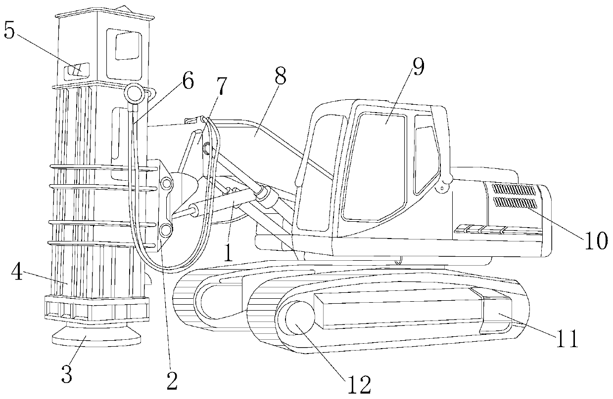
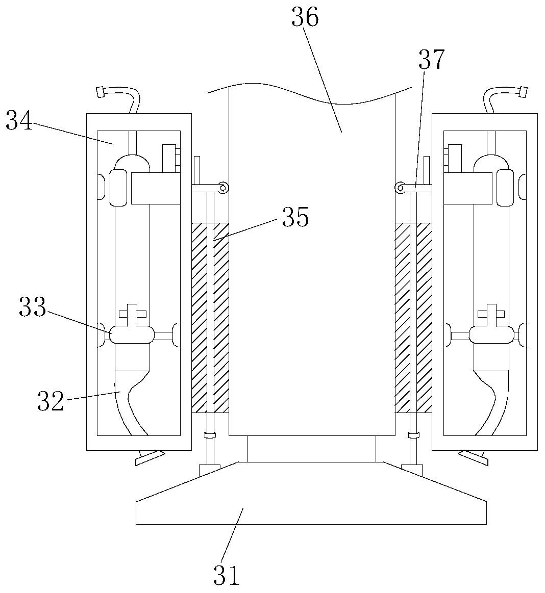
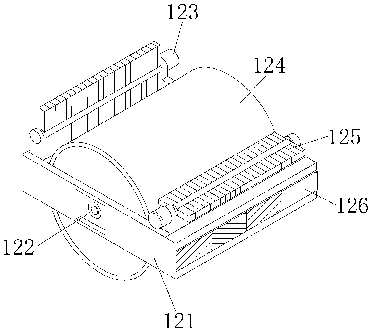
[0033] see Figure 1-Figure 9 , the present invention provides a technical solution: a rapid foundation compaction machine for construction engineering, the structure of which includes a hydraulic rod 1, a support plate 2, a compaction hammer 3, a hammer body 4, a counterweight 5, a connecting wire 6, and a shock absorber 7. Boom 8, cab 9, car body 10, walking crawler belt 11, and flattening device 12. The hydraulic rod 1 is fitted and connected to the boom 8, and the front end of the boom 8 is provided with a support plate 2. The rear end of the support plate 2 is closely attached to the hammer body 4. The upper and lower ends of the hammer body 4 are respectively provided with a compacting hammer 3 and a counterweight 5, and the three are arrang...


PUM


Abstract

The invention discloses a foundation quick rammer compactor for constructional engineering. The foundation quick rammer compactor structurally comprises a hydraulic rod, a supporting plate, a tampinghammer, a hammer body, a balancing weight, a connecting wire, a shock absorber, a mobile arm, a cab, a vehicle body, a walking crawler belt and a flattening device. After the improvement, when the tamping is carried out; a worker controls the vehicle body to operate the mobile arm to adjust the hammer body; the mobile push plate is used for extruding downwards, so that the body assists the pressing plate to press the compaction hammer downwards to compact the foundation, the compaction impact force of the compaction hammer is reduced through the adjusting element and the buffer air bag, the influence of the impact feeling on construction personnel is reduced, floating and sinking around are treated through the dust suction pipe, and the working environment during compaction is improved. After the ground is hit, the pressing force of the pressing roller and the rolling wheel is adjusted through the adjusting block, the pressing roller and the rolling wheel move through the rotating shaft, the flattening wheel is assisted in flattening the foundation surface, the uneven phenomenon of the foundation is prevented, the flattening wheel compacts gravel on the ground on the foundation, and the tamping effect is improved.

Description

technical field [0001] The invention relates to the field of building construction, in particular to a fast foundation compacting machine for building engineering. Background technique [0002] A tamping machine is a kind of special tamping equipment used for compacting fillings or soft foundations in construction or road construction. It is usually installed on an excavator or a loader; when the existing tamping machines are used for tamping, they have the following deficiencies : [0003] 1. When the tamping machine is tamping the foundation, due to the large impact force, the impact and vibration will affect the construction personnel, which will cause injuries to the construction personnel for a long time, and the rammer will splash up and down around the rammer during tamping. The ups and downs caused by the impact will accumulate more and more, seriously affecting the working environment of the surrounding staff; [0004] 2. When the existing tamping machine hits the...

Claims


Application Information

Patent Timeline
Patent Type & Authority Applications(China)
IPC IPC(8): E01C19/41E02D3/02E02D3/046E02D3/026
CPCE01C19/41E01C2301/50E02D3/02E02D3/026E02D3/046
Inventor 袁军国
Owner 袁军国
Why Eureka
Try Eureka