Paddy field stubble burying cultivator

A technology for tilling machines and paddy fields, applied in the field of farmland tilling machines, can solve the problems of increasing the number of round trips, affecting land leveling, and high operating costs, and achieving the effects of improving work efficiency, increasing the number of round trips, and reducing operating costs.

Active Publication Date: 2013-05-22
泰州樱田农机制造有限公司
View PDF4 Cites 11 Cited by
  • Summary
  • Abstract
  • Description
  • Claims
  • Application Information

AI Technical Summary

Problems solved by technology

Although existing paddy field rakes, paddy field stubble burying and paddle preparation machines and double-roller stubble removal and soil preparation machines can play the role of stubble burial to varying degrees, there are the following major defects: 1. Paddy field rakes and paddy field stubble paddle paddles It can only be operated on the cultivated land, that is, the field must be plowed once, soaked in water for 12 hours before the machine can be used for operation. There are many farming links and the cost of farming is high; Because it is a double-shaft knife roller (rotary tillage by the front roller, and stubble removal by the rear roller), the structure is complex, the load is heavy, and the operating cost is high;
[0004] 2. The existing paddy field cultivator trailer is a long and narrow strip-shaped plate structure. The trailer is generally in a fixed flat or approximately flat state, and the ground is leveled by using its bottom plane
This kind of pallet structure has disadvantages: if the original ground is uneven and the height difference is large, the horizontal or nearly horizontal pallet cannot move the soil on the higher ground to a lower place due to its thickness limitation. ;The carriage is in a fixed flat or nearly flat state, and cannot exert active force on the ground, let alone adjust the pressure of the carriage on the ground according to the ground conditions. Therefore, it is impossible to obtain a better leveling effect;
[0005] 3. The existing paddy field cultivator dragger is a long and narrow strip-shaped plate structure, which is basically the same width as the rotary tillage paddle machine. The generated mud flows out from both sides of the drag plate, causing the soil in the middle to be lost to both sides, so that the raked field will have a concave phenomenon, which will affect the flatness of the land; The height is uneven. In order to make the joints of the paddy field ground easily high and low, the paddy field cultivator needs to increase the number of round trips, and the work efficiency is low;
[0006] Four, the connection structure of the existing paddy field tiller and the rear end of the frame is that the dragger is directly fixedly connected to the rear end of the frame. The shortcoming of this structure is: when the paddy field tiller works, the paddy field is uneven As the tillage paddle machine tilts with the tractor, the frame will also tilt with the rotary tillage paddle machine. Since the rear end of the carriage is rigidly connected with the frame, it will inevitably cause the original horizontal contact of the carriage to the ground. Tilting, which will cause the deformation of the carriage, and also affect the flatness of the harrowing land. When the carriage is seriously deformed, it will damage the paddy field cultivator;
The advantage of this kind of transmission mechanism is that the force on the rotating shaft of the paddy field tillage machine is relatively balanced, but the disadvantages are more prominent: 1. There is a blind area in the middle of the paddy field tillage machine; 2. It is inconvenient to maintain and adjust

Method used


Image

  • Paddy field stubble burying cultivator
  • Paddy field stubble burying cultivator
  • Paddy field stubble burying cultivator

Examples


Embodiment Construction

[0051] The present invention will be further described below according to the accompanying drawings and in conjunction with the embodiments.

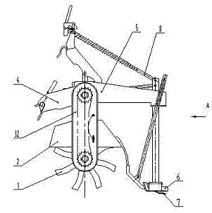
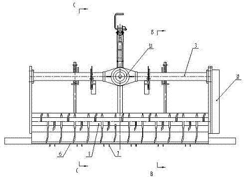
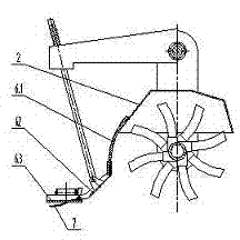
[0052] Such as figure 1 , figure 2 The shown paddy field stubble tiller includes a rotary paddle mechanism 1, a casing 2, a transmission system 3, a suspension assembly 4, a frame assembly 5, and a carriage assembly 6; the transmission system 3 includes Two-stage transmission mechanism, the former stage is the bevel gear transmission mechanism 3.1 in the middle of the cultivator, and the latter stage is the chain transmission mechanism 3.2; the drag plate assembly 6 is connected to the rear end of the casing 2; the chain transmission mechanism 3.2 Set on one side of the tiller, the bevel gear transmission mechanism 3.1 transmits the power to the chain transmission mechanism 3.2 through the transmission shaft, and the chain transmission mechanism 3.2 transmits the power to the rotary paddle mechanism 1. In this embodiment, the chai...


PUM


Abstract

The invention discloses a paddy field stubble burying cultivator. The paddy field stubble burying cultivator comprises a rotary tillage and beating mechanism, a casing, a transmission system, a suspension assembly, a rack assembly and a carriage assembly, wherein the transmission system comprises two stages of transmission mechanisms, namely a front bevel gear transmission mechanism and a rear chain transmission mechanism. The cultivator is characterized in that the chain transmission mechanism is arranged on one side of the cultivator; a carriage flexible buffer and compensation connection structure is arranged between a secondary carriage of the carriage assembly and the casing; a stubble burying structure is arranged on a primary carriage and comprises a compression bar overhung on the lower end face of the primary carriage; a left carriage and a right carriage are respectively arranged on the two sides of the primary carriage to form an assembled carriage structure; a primary carriage adjusting mechanism is arranged on the primary carriage and comprises a plane four-bar mechanism and a limiting structure; and the plane four-bar mechanism is formed by a support frame component, an oblique push bar, a supporting bar and a vertical bar. The paddy field stubble burying cultivator is reasonable in structure and convenient to adjust and maintain, works without dead zones, can complete rotary tillage, beating, stubble burying and harrowing in one step and has high ground flatness.

Description

technical field [0001] The invention relates to a farmland tillage machine matched with a tractor, in particular to a paddy field tillage machine matched with a tractor and integrating rotary tillage, stubble burying, oar beating and land harrowing. Background technique [0002] With the development of agriculture, paddy field tillage machines matched with tractors are widely used in agricultural production. Existing paddy field tillage machines have defects in the following aspects during use: [0003] 1. In order to improve the soil properties of cultivated land and avoid pollution caused by straw burning, it is the best solution to implement "straw returning to the field". For this reason, developing efficient and applicable harrowing and stubble-burying machinery is an urgent problem to be solved in the agricultural machinery front. Although existing paddy field rakes, paddy field stubble burying and paddle preparation machines and double-roller stubble removal and soil...

Claims


Application Information

Patent Timeline
Patent Type & Authority Applications(China)
IPC IPC(8): A01B49/02A01B35/18A01B35/20
Inventor 曹冬林
Owner 泰州樱田农机制造有限公司
Why Eureka
Try Eureka