Dither amplitude correction for constant current drivers

a constant current driver and amplitude correction technology, applied in the direction of pulse manipulation, electric control, pulse technique, etc., can solve the problems of reducing the effectiveness of dither waveform and more expensive switching constant current drivers, and achieve the effect of improving the driver circui

Active Publication Date: 2006-10-19
VISTEON GLOBAL TECH INC
View PDF23 Cites 10 Cited by
  • Summary
  • Abstract
  • Description
  • Claims
  • Application Information

AI Technical Summary

Benefits of technology

[0010] As disclosed above, there is a need to compensate for the high impedance load characteristics in certain implementations of hysteretic switching constant current drivers. As described below, the driver signal of a switching constant current driver circuit may be modified in such a way that retains important dither characteristics and improves system level performance.

Problems solved by technology

Switching constant current driver can be more expensive, but minimize heat generation.
Unfortunately, when the load impedance increases to a point where the primary switching frequency approaches the desired dither frequency, the effectiveness of the dither waveform can be greatly reduced due to a reduction in the dither amplitude.

Method used


Image

  • Dither amplitude correction for constant current drivers
  • Dither amplitude correction for constant current drivers
  • Dither amplitude correction for constant current drivers

Examples


Embodiment Construction

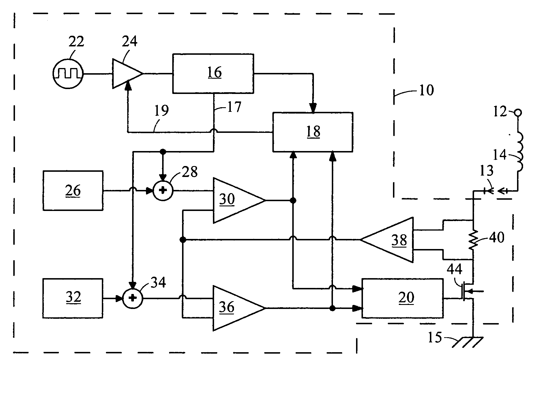
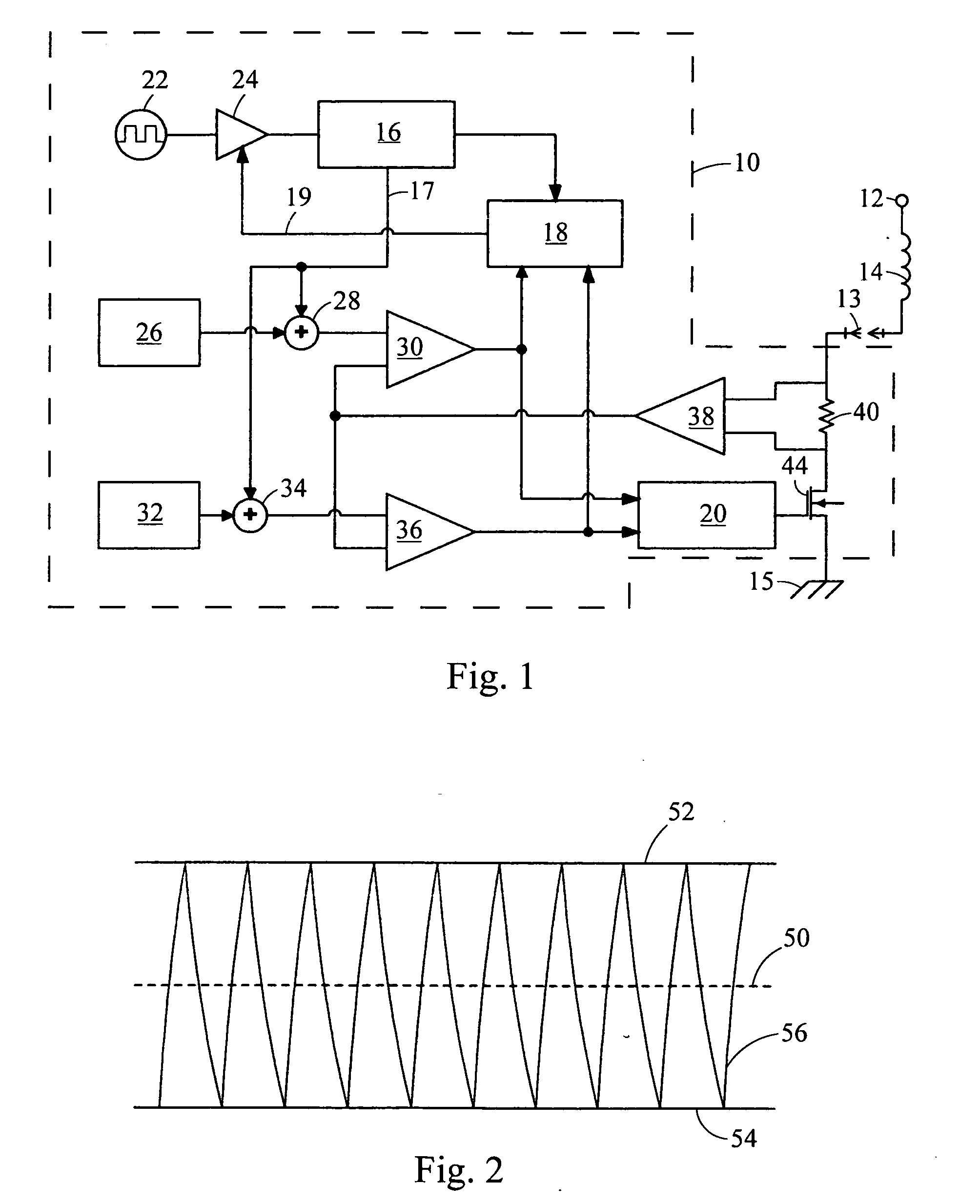
[0021] Referring now to FIG. 1, a driver circuit, shown as a switched driver circuit 10, embodying the principles of the present invention is illustrated therein. As its primary components, the switched driver circuit 10 includes a dither generator circuit 16, a dither correction circuit 18, and a gate control circuit 20.

[0022] A solenoid 14 is connected to a power supply 12. The switched driver circuit 10 is connected in electrical series with the solenoid 14 and provides an electrical path to ground 15 for the solenoid 14. In addition, an electrical connector 13 may be used to couple the solenoid 14 to the switched driver circuit 10. The switched driver circuit 10 is configured to provide a constant current through the solenoid 14 using a hysteretic approach. Further, the switched driver circuit 10 implements a dither waveform to oscillate the pintle of the solenoid 14.

[0023] To implement the dither waveform, the clock generator 22 provides a clock signal to the buffer 24. The b...


PUM


Abstract

In satisfying the above need, as well as overcoming the enumerated drawbacks and other limitations of the related art, the present invention provides an improved switched driver circuit. As disclosed above, there is a need to compensate for the high impedance load characteristics in certain implementations of hysteretic switching constant current drivers. The switching waveform of switching constant current driver circuits may be modified in such a way that retains the important dither characteristics and improves system level performance.

Description

BACKGROUND [0001] 1. Field of the Invention [0002] The present invention generally relates to switched driver circuit for generating a switched drive signal including a dithering signal. [0003] 2. Description of Related Art [0004] Many electronic control module products make use of constant current output driver ICs. The purpose of these circuits is to provide a constant current through a system load of interest. In automotive applications, typical loads are: transmission pressure control solenoids, idle bypass air valves, etc. Constant current driver circuits are usually implemented using either “linear” or “switching” approaches. Linear constant current drivers are usually less expensive, but generate significant heat. Switching constant current driver can be more expensive, but minimize heat generation. [0005] When using constant current drivers, another common feature is a superimposed “dither” frequency. The dither frequency is much less than primary switching frequency. The di...

Claims


Application Information

Patent Timeline
Patent Type & Authority Applications(United States)
IPC IPC(8): H03B1/00
CPCF02D41/1408H02M2003/1555H02M2001/0025H02M3/156H02M1/0025H02M3/1555
Inventor SWANSON, DIRK E.LADUKE, MATTHEW T.HOPPER, MARK L.BOLDUC, ROBERT J.
Owner VISTEON GLOBAL TECH INC
Why Eureka
Try Eureka