
Method for automatically acquiring rotating speed of rotating equipment in abnormal state

A technology for rotating equipment and abnormal states, applied in linear/angular velocity measurement, machine/structural component testing, velocity/acceleration/impact measurement, etc., can solve cost factors, difficulty in construction, difficulty in speed measurement, difficulty in large-scale application, To solve problems such as heavy workload, to achieve the effect of convenient calculation method, avoiding dependence on experience, and increasing accuracy and reliability

Pending Publication Date: 2022-04-19
南京凯奥思数据技术有限公司
View PDF0 Cites 0 Cited by
  • Summary
  • Abstract
  • Description
  • Claims
  • Application Information

AI Technical Summary

Problems solved by technology

One is to directly collect speed data by adding speed sensors, eddy current sensors, and photoelectric speed sensors. However, this method is difficult to apply on a large scale due to the limitations of cost factors, construction difficulty, and difficulty in measuring speed in wireless systems.
The second is to collect vibration signals by installing vibration sensors, and then the engineer determines the speed of the equipment by analyzing the frequency spectrum corresponding to the vibration signal. In this method, the accuracy of speed recognition depends on the experience of the engineer, which is highly subjective. In addition, engineers also need to observe and compare a large number of captured vibration signals, which is a heavy workload and prone to errors

Method used


Image

  • Method for automatically acquiring rotating speed of rotating equipment in abnormal state

Examples


Embodiment Construction

[0023] In order to make the purpose, technical solution and advantages of the present invention more clear, the embodiments of the present invention will be described in detail below in conjunction with the accompanying drawings.

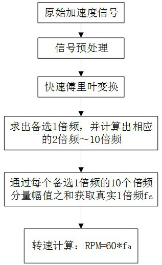
[0024] The method for automatically obtaining the rotating speed of rotating equipment is characterized in that it comprises the following steps:

[0025] S1. Obtain the original acceleration signal of the rotating equipment under abnormal state through the acceleration sensor;

[0026] S2. Preprocessing the original acceleration signal in step S1;

[0027] S3. Perform fast Fourier transform on the signal preprocessed in step S2 to obtain an acceleration frequency domain signal;

[0028] S4, in the frequency domain signal obtained in step S3, select the frequency corresponding to the top five of the peak value of the amplitude in turn as an alternative 1 multiplier frequency f i,1 (i=1~5), through each alternative 1 multiplier, calculate its corre...


PUM


Abstract

The invention relates to the technical field of fault diagnosis of rotating mechanical equipment, and discloses a method for automatically acquiring the rotating speed of rotating equipment in an abnormal state, which comprises the following steps of: preprocessing an acceleration signal, performing fast Fourier transform to obtain a frequency spectrum, and obtaining a plurality of alternative one-time frequency multiplication by using a peak point of the frequency spectrum; and then the alternative first frequency multiplication is utilized to solve the corresponding second frequency multiplication to the tenth frequency multiplication, the real first frequency multiplication is judged according to the sum of the amplitudes of the ten frequency multiplication components, and finally the rotating speed of the rotating equipment is calculated according to a formula. According to the method, the rotating speed value can be automatically obtained, dependence on experience of professional engineers is avoided, and the calculation mode is more convenient and accurate.

Description

technical field [0001] The invention belongs to the technical field of fault diagnosis of rotating mechanical equipment, and in particular relates to a method for automatically obtaining the rotational speed of rotating equipment in an abnormal state. Background technique [0002] As an important mechanical equipment in modern industry, rotating machinery is widely used in industrial production. Once the rotating equipment fails, it will cause huge economic losses. Under the background of big data and artificial intelligence, predictive operation and maintenance of rotating equipment is the key direction of the development of major enterprises. In the field of predictive operation and maintenance, it is often necessary to accurately obtain the rotational speed of rotating equipment under abnormal conditions. Used to determine the type of equipment failure. [0003] At this stage, there are mainly two methods for obtaining the rotational speed. One is to directly collect s...

Claims


Application Information

Patent Timeline
IPC IPC(8): G01M99/00G01P3/00G06F17/14
CPCG01M99/004G01P3/00G06F17/14
Inventor 徐徐孔双双孙磊杨世飞邹小勇刘宗斌
Owner 南京凯奥思数据技术有限公司
Learn More