High-frequency transformer capable of safely dissipating heat
A high-frequency transformer and safe technology, applied in the field of high-frequency transformers, can solve problems such as inability to work, inability to cool down and dissipate heat, and achieve the effect of avoiding high temperature
- Summary
- Abstract
- Description
- Claims
- Application Information
AI Technical Summary
Problems solved by technology
Method used
Image
Examples
Embodiment 1
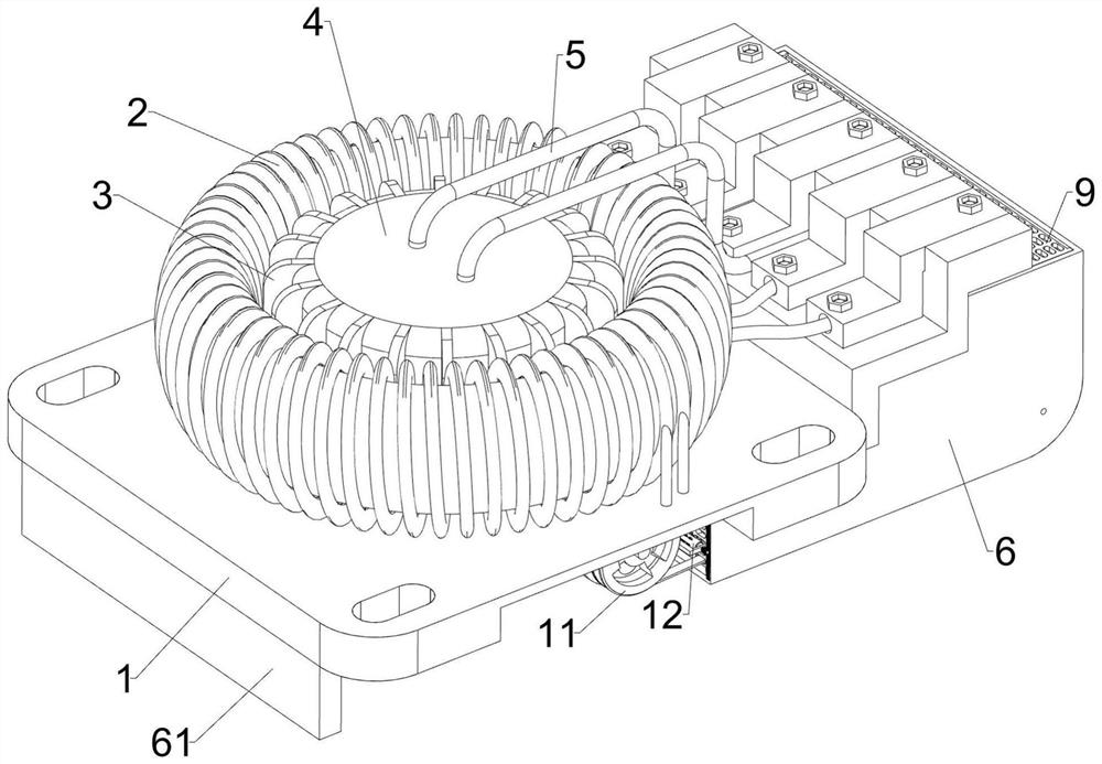
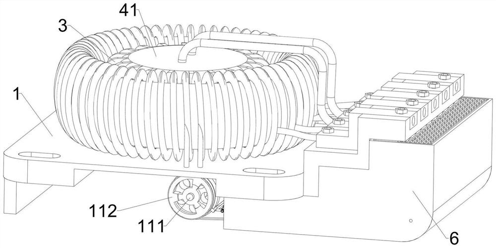
[0033] See also a high frequency transformer that can safely dissipate heat, including a base 1, a high frequency transformer 2, a heat-absorbing fin 3, a thermal conductive mechanism 4 and a heat dissipation mechanism 5 Figure 1 、 Figure 2 、 Figure 3 、 Figure 8 、 Figure 9 and Figure 10 As shown, the base 1 top is installed with a high-frequency transformer 2, the base 1 is installed with a thermal conductive mechanism 4, the thermal conductive mechanism 4 is installed at intervals with twenty heat-absorbing fins 3, when the high-frequency transformer 2 is constantly operating, the heat-absorbing fin 3 can realize the heat dissipation of the high-frequency transformer 2, the base 1 is installed with a heat dissipation mechanism 5, the heat dissipation mechanism 5 is connected with the heat conductive mechanism 4, when the heat dissipation mechanism 5 is operated, the heat dissipation mechanism 5 can realize the heat extraction.
[0034] Thermal conductivity mechanism 4 includes a...
Embodiment 2
[0040] On the basis of Example 1, further comprising a frame 6, a vertical plate 61, a fixing strip 7 and an exhaust fan 8, see Figure 1 、 Figure 2 、 Figure 3 and Figure 6 As shown, the base 1 bottom left side is installed by welding the way of connection 61, the vertical plate 61 can be installed to provide support, the base 1 top right side is installed with a frame 6, the heat dissipation fin 52 is located in the box 6, the box 6 can realize the diversion of heat, the frame 6 inside the front and rear sides of the left side symmetry is installed by welding the way of installation of the fixing bar 7, the number of upper side fixing strip 7 and the lower side fixing bar 7 are two, the installation of three exhaust fans between the four fixing strips 7 is evenly spaced 8, When the exhaust fan 8 is started, the exhaust fan 8 may realize the discharge of air into the frame 6.
[0041] Also included is a mesh plate 9 and a filter plate 10, see Figure 1 and Figure 3As shown, the u...
Embodiment 3
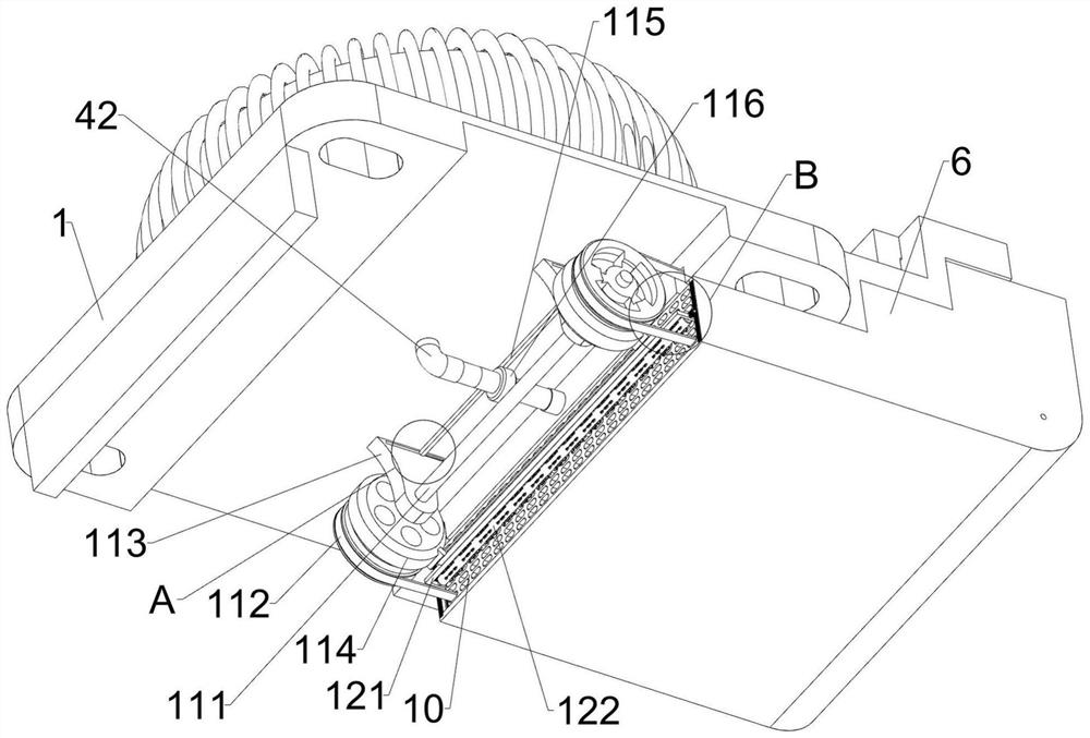
[0045] On the basis of Example 1 and Example 2, further comprising a diversion mechanism 11, a diversion mechanism 11 comprising a hinge 111, a transmission component 112, a fixing plate 113, a drive wheel 114, a movable rod 115, a check valve 116, a first spring 117, a guide shaft 118 and a wind guide wheel 119, see Figure 1 、 Figure 2 、 Figure 3 、 Figure 4 、 Figure 6 、 Figure 9 、 Figure 10 and Figure 11 As shown, the L-type pipe 42 is installed with a check valve 116, the check valve 116 can realize the control of the water in the L-type pipe 42, the base 1 bottom left side symmetry is installed by welding the way of connection 113, the front and rear sides of the fixed plate 113 between the upper part of the sliding type of the threading has a movable rod 115, the bottom middle of the movable rod 115 and the check valve 116 top fixed connection, when the movable rod 115 moves, the movable rod 115 can realize the drive check valve 116 to move, The first spring 117 is connected ...
PUM
 Abstract
Description
Claims
Application Information
 - R&D
- Intellectual Property
- Life Sciences
- Materials
- Tech Scout
- Unparalleled Data Quality
- Higher Quality Content
- 60% Fewer Hallucinations
Browse by: Latest US Patents, China's latest patents, Technical Efficacy Thesaurus, Application Domain, Technology Topic, Popular Technical Reports.
© 2025 PatSnap. All rights reserved.Legal|Privacy policy|Modern Slavery Act Transparency Statement|Sitemap|About US| Contact US: help@patsnap.com


