

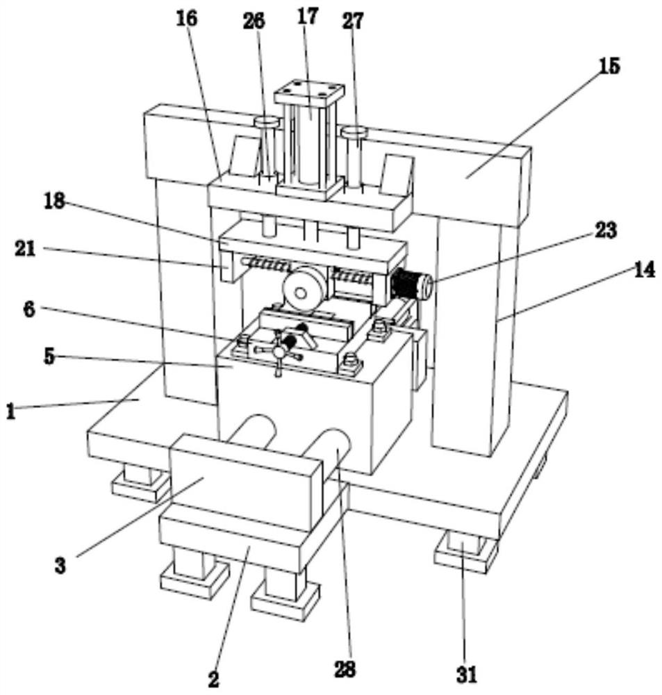
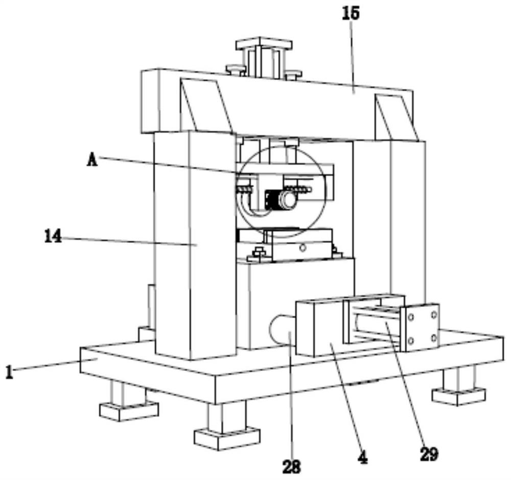
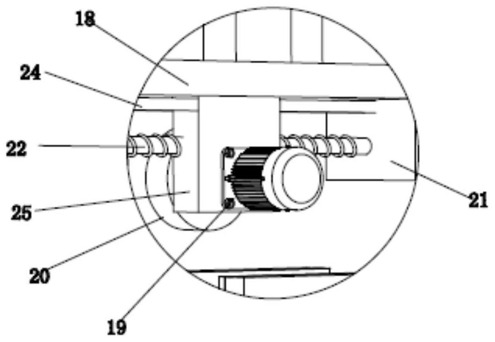
Surface polishing device for power electronic component manufacturing
A technology for power electronics and components, applied in the field of surface grinding devices for the manufacture of power electronic components, can solve the problems of high labor intensity, low grinding efficiency, unsatisfactory grinding effect, etc., and achieves wide applicability and high grinding efficiency. Effect
- Summary
- Abstract
- Description
- Claims
- Application Information
AI Technical Summary
Problems solved by technology
Method used
Image

Examples
Embodiment Construction
[0019] The present invention will be described in further detail below in conjunction with the accompanying drawings.
[0020] The specific implementation manner of the present invention will be further described below in conjunction with the accompanying drawings. Wherein the same components are denoted by the same reference numerals.
[0021] It should be noted that the words "front", "rear", "left", "right", "upper" and "lower" used in the following description refer to the directions in the drawings, and the words "inner" and "outer ” refer to directions towards or away from the geometric center of a particular part, respectively.
[0022] In order to make the content of the present invention more clearly understood, the technical solutions in the embodiments of the present invention will be clearly and completely described below in conjunction with the drawings in the embodiments of the present invention.
[0023] In conjunction with the accompanying drawings, a surface...
PUM
 Abstract
Description
Claims
Application Information