Convenient-to-assemble bill clamping device for accountant
A technology for holding devices and bills, which is used in folders, printing, etc., can solve the problems of inconvenient operation and assembly, affecting the stability of bills, inconvenient cleaning and removing dust on bills, etc. The effect of convenient operation
- Summary
- Abstract
- Description
- Claims
- Application Information
AI Technical Summary
Problems solved by technology
Method used
Image

Examples
Embodiment 1
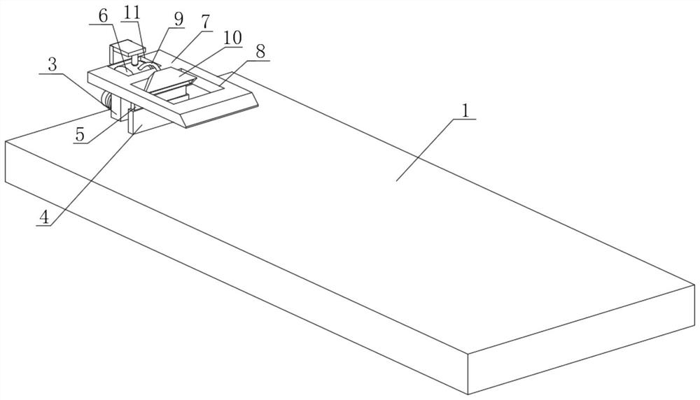
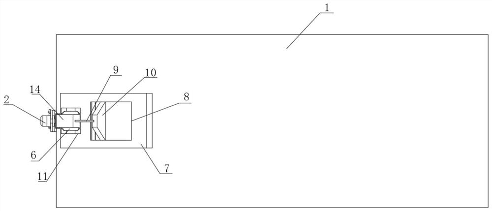
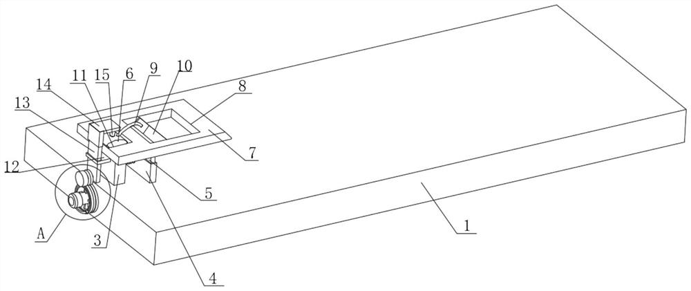
[0031] see Figure 1-Figure 8 , the present invention provides a technical solution: an accounting bill clamping device that is easy to assemble, including a device body 1, an adjustment device 2 is provided on one side of the device body 1, and a support plate is fixedly connected to the left side of the top of the device body 1 3. The top of the device body 1 and the right side of the support plate 3 are fixedly connected with a movable cylinder 4, the top of the movable cylinder 4 is plugged with a movable plate 5, the top of the support plate 3 is provided with a pressing air bag 6, and the top of the movable plate 5 A clamping plate 7 is provided, and the inside of the clamping plate 7 is provided with a blowing port 8 and a square opening 11. One side of the pressing airbag 6 is fixedly connected with a blowing pipe 9, and the side of the blowing pipe 9 away from the pressing airbag 6 is fixedly connected with a blowing pipe 9. The head 10, the inner wall of the blower h...
Embodiment 2
[0035] see Figure 5-Figure 6 and Figure 8 As shown, on the basis of Embodiment 1, the present invention provides a technical solution: the outer wall of one side of the magnetic slider 211 is magnetically attracted to the inner wall of the magnetic groove 207, and the side of the rotating ring 205 close to the sliding column 206 is provided with a limited position. Slot, the inner wall of the limiting groove is slidingly connected with the outer wall of the sliding column 206, wherein the limiting groove plays a role of limiting the sliding column 206, so that the sliding column 206 is more stable when moving, and the inside of the device body 1 is provided with a The rotating hole that the rod 202 is adapted to, wherein, the setting of the rotating hole is to facilitate the stable rotation of the rotating rod 202 .
[0036] In this embodiment, the limit groove provided on the rotating ring 205 plays a role in limiting the position of the sliding column 206, making the slid...
Embodiment 3
[0038] see Figure 5 and Figure 7 As shown, on the basis of Embodiment 1 and Embodiment 2, the present invention provides a technical solution: the other side of the support plate 3 is fixedly connected with a telescopic rod 16, and the outer wall of the telescopic rod 16 is sleeved with a buffer spring 17, and the telescopic The side of the rod 16 away from the support plate 3 is fixedly connected to one side of the outer wall of the movable cylinder 4, and the upper and lower outer walls of the movable cylinder 4 are respectively slidably connected to the bottom of the clamping plate 7 and the top of the device body 1, wherein when the movable cylinder 4 When sliding along the top of the device body 1, it is convenient to extrude the telescopic rod 16 and the buffer spring 17, and the bottom inner wall of the movable cylinder 4 is fixedly connected with a return spring 18, and the top of the return spring 18 is fixedly connected with the bottom of the movable plate 5, where...
PUM
 Abstract
Description
Claims
Application Information
 - R&D Engineer
- R&D Manager
- IP Professional
- Industry Leading Data Capabilities
- Powerful AI technology
- Patent DNA Extraction
Browse by: Latest US Patents, China's latest patents, Technical Efficacy Thesaurus, Application Domain, Technology Topic.
© 2024 PatSnap. All rights reserved.Legal|Privacy policy|Modern Slavery Act Transparency Statement|Sitemap