
Pipeline laying and concrete structure in high-fall pipe well and construction method

A technology of concrete structure and construction method, which is applied in basic structure engineering, underwater structure, pipe/pipe joint/pipe fitting, etc., can solve the problem of small space of high drop shaft and achieve the effect of saving investment

Pending Publication Date: 2022-04-22
POWERCHINA HUADONG ENG COPORATION LTD
View PDF0 Cites 0 Cited by
  • Summary
  • Abstract
  • Description
  • Claims
  • Application Information

AI Technical Summary

Problems solved by technology

[0005] The invention provides a pipeline laying, concrete structure and construction method in a high-drop tube well, aiming to solve the problem that the space of a high-drop shaft is small and personnel cannot enter the shaft to install pipelines, and to ensure the safety of personnel and pipeline installation during pipeline installation. Welding quality and the feasibility of the test plan; at the same time, after the pipeline installation is completed, design a reasonable and safe high-drop shaft backfill concrete structure, and determine the sequence and timing of concrete pouring to ensure the installed drainage pipeline and well structure Safety

Method used


Image

  • Pipeline laying and concrete structure in high-fall pipe well and construction method
  • Pipeline laying and concrete structure in high-fall pipe well and construction method
  • Pipeline laying and concrete structure in high-fall pipe well and construction method

Examples


Embodiment Construction

[0036] The present invention will be further described below in conjunction with the accompanying drawings and specific embodiments.

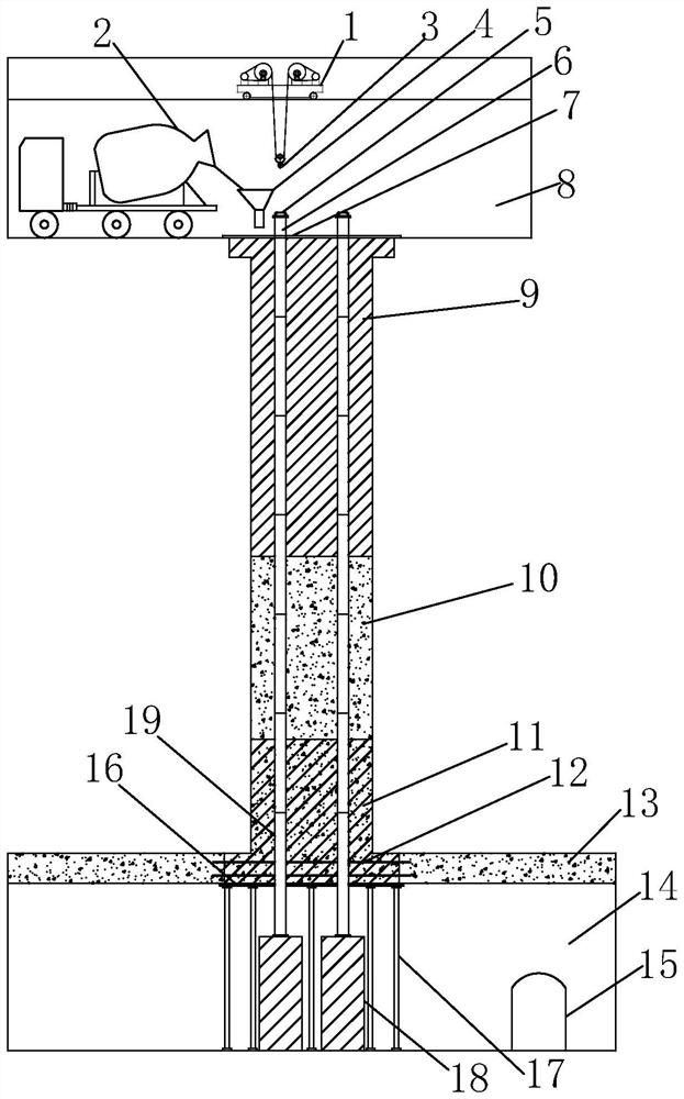
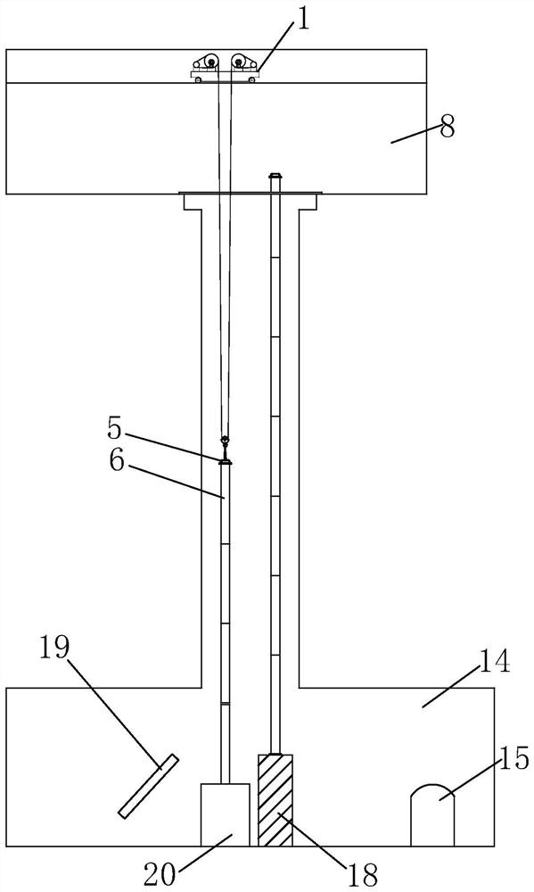
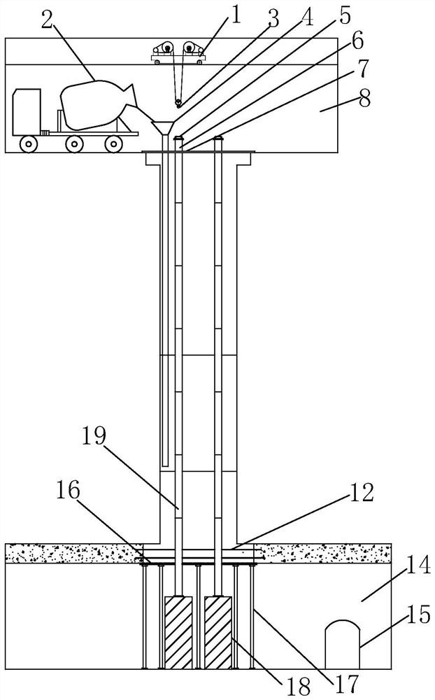
[0037] Such as figure 1 , figure 2 As shown, the pipeline laying and concrete structure in a high-drop pipe well of the present invention include an upper equipment room 8, a lower equipment room 14, a high-drop vertical shaft, a plurality of water supply and drainage steel pipes 6, and the high-drop vertical shaft in the upper equipment room 8 Excavated between the lower equipment room 14, the drainage steel pipe 6 is vertically arranged in a high-drop vertical shaft, and a backfill concrete structure is arranged in the high-drop vertical shaft.

[0038] The backfilled concrete structure includes from top to bottom the concrete 9 of the first section of the shaft with a "T"-shaped concrete structure, the second-section concrete 10 of the shaft with a cylindrical concrete structure, and the third-section concrete 11 of the vertical shaft with...


PUM


Abstract

The invention discloses a pipeline laying and concrete structure in a high-fall pipe well and a construction method, and aims to solve the problem that a high-fall vertical shaft is small in space and personnel cannot enter the vertical shaft to install a pipeline and guarantee the safety of the personnel, the welding quality of the pipeline and the feasibility of a test scheme in the pipeline installation process. The structure comprises an upper equipment room, a lower equipment room, a high-fall vertical shaft and a plurality of water supply and drainage steel pipes, the water supply and drainage steel pipes are vertically arranged in the high-fall vertical shaft, and a backfill concrete structure is arranged in the high-fall vertical shaft. The construction method comprises the steps that firstly, an upper-layer equipment room and a lower-part equipment room are excavated, and a high-fall vertical shaft is excavated; hoisting water supply and drainage steel pipes; and the excavated high-fall vertical shaft is subjected to segmented concrete backfilling. When the fall of the pipe well exceeds a certain height, the pipe well can be divided into several sections of high-fall pipe wells, and similar or identical pipeline laying and concrete structures and construction methods are arranged.

Description

technical field [0001] The invention relates to the technical field of water conservancy and hydropower engineering, in particular to a pipeline laying in a high-drop tube well, a concrete structure and a construction method. Background technique [0002] In water conservancy and hydropower projects, a large number of underground caverns are set up to arrange equipment to meet the needs of facility operation, which also includes more water supply systems, leakage or maintenance drainage systems. These water supply and drainage systems are affected or limited by the tail water level of the downstream river channel, and the water supply and drainage pipelines are all set above the highest downstream tail water level, because the underground caverns are isolated from the downstream tail water level by thick rock mass. In order to find a simple, smooth, and safe drainage line, sometimes vertical shafts with a drop of tens of meters or even hundreds of meters have to be drilled i...

Claims


Application Information

Patent Timeline
IPC IPC(8): E02D29/045E02D19/10E02D15/02F16L3/00
CPCE02D29/045E02D19/10E02D15/02F16L3/00Y02E10/20
Inventor 方杰曹春建李胜兵郑应霞许志翔吴胜华方晓红和扁
Owner POWERCHINA HUADONG ENG COPORATION LTD
Learn More