Fabricated wallboard mounting method capable of quickly adjusting flatness of wall surface
An installation method and flatness technology, which are applied in the field of prefabricated wall panel installation that can quickly adjust the flatness of the wall surface, can solve the problems of slowing down the hoisting speed and trouble, and achieve the goal of improving the installation speed, facilitating installation, and ensuring horizontal and straight installation. Effect
- Summary
- Abstract
- Description
- Claims
- Application Information
AI Technical Summary
Problems solved by technology
Method used
Image
Examples
Embodiment 1
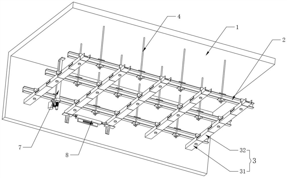
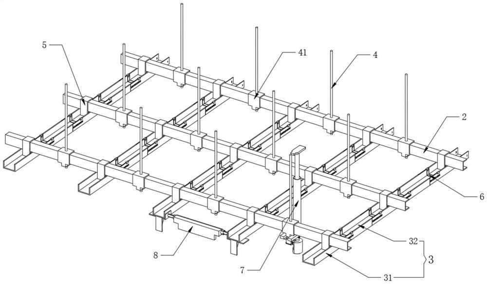
[0050] Refer to attached figure 2 , the auxiliary steel frame keel assembly 3 also includes an end steel frame 31, one end of the end steel frame 31 is equidistantly fixedly connected to the inner wall of one side of the building floor 1, the other end of the end steel frame 31 is spliced with a splicing steel frame 32 one by one, and the end Both the steel frame 31 and the spliced steel frame 32, and between the two spliced steel frames 32 are connected by the fixed fixture 6;
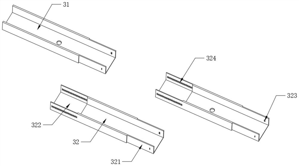
[0051] Refer to attached image 3 One end of the end steel frame 31 and one end of the splicing steel frame 32 are fixedly provided with an insertion end 321, and the other end of the splicing steel frame 32 is fixed with an access slot 322 inside, and the insertion end 321 is inserted into the adjacent access slot 322. Inside, the two side walls of the insertion end 321 are fixed with positioning holes 323, and the two side walls of the access groove 322 are fixed with a row of holes 324 at e...
Embodiment 2
[0057] Refer to attached Figure 9 , the wall leveling aids 8 are spliced with the two end steel frames 31 one by one, and the wall leveling aids 8 are attached to the inner wall of the building floor 1 on which the end steel frames 31 are installed, and the wall leveling aids 8 also include a main body 801 , both ends of the main body 801 are slidingly installed with inner rods 804, and the ends of the two inner rods 804 are fixedly provided with L-shaped support platforms 805, and the lower surfaces of the L-shaped support platforms 805 are fixedly provided with support brackets 806, In addition, the main pipe body 801 and the support frame 806 are both fitted to the inner wall of the building floor 1, and the L-shaped support platform 805 is fitted to the end steel frame 31. After the first end steel frame 31 is fixed, the wall is leveled. The auxiliary device 8 fits the wall surface, and ensures that the support frame 806 is close to the wall surface, and the first end s...
Embodiment 3
[0061] Refer to attached Figure 5 , the leveling installer 7 is spliced with the boom 4 one by one, the boom 4 is fixedly connected to the main steel frame keel 2 through the boom connector 41 connected at the bottom end, and the boom connector 41 is set on the main steel frame keel 2 The lower surface of the boom connector 41 is fixedly provided with a leveling boss 42 .
[0062] Refer to attached Figure 5 , the leveling installer 7 also includes an outer screw tube 701, the inner screw rod 702 is connected to the inner movable screw of the outer screw tube 701, and the top of the inner screw rod 702 is fixedly connected with a top support plate 703, and the top support plate 703 fits inside the building floor 1 On the ceiling surface, a fork plate 704 is fixed on the outer wall of the bottom end of the outer coil 701, and the fork plate 704 is movably sleeved on the outer surface of the leveling boss 42, and the inner screw 702 is rotated to adjust the top support plate...
PUM
 Abstract
Description
Claims
Application Information
 - R&D
- Intellectual Property
- Life Sciences
- Materials
- Tech Scout
- Unparalleled Data Quality
- Higher Quality Content
- 60% Fewer Hallucinations
Browse by: Latest US Patents, China's latest patents, Technical Efficacy Thesaurus, Application Domain, Technology Topic, Popular Technical Reports.
© 2025 PatSnap. All rights reserved.Legal|Privacy policy|Modern Slavery Act Transparency Statement|Sitemap|About US| Contact US: help@patsnap.com


