
Disc buckle type cantilever support system

A support system and cantilever frame technology, which are applied to the scaffolding supported by the building structure, the accessories of the scaffolding, the support of the building structure, etc., can solve the problems of difficult installation and adjustment, affecting the installation of the frame structure, complex structure

Pending Publication Date: 2022-04-22
QINGDAO JUNYING EQUIP TECH CO LTD
View PDF0 Cites 0 Cited by
  • Summary
  • Abstract
  • Description
  • Claims
  • Application Information

AI Technical Summary

Problems solved by technology

[0002] With the popularization of disc-buckled scaffolding and building metal safety nets, structural parts based on connecting discs and external building metal safety nets also need to be developed and designed. At present, they are installed based on fastener-type connectors of vertical poles and horizontal poles. These parts have complex structures, many matching parts, high cost, difficult installation and adjustment, poor positional accuracy, and often interfere with structural parts, which is very inconvenient. For an installation node, one-to-two, one-to-four, and side-by-side installations may occur There are no standard parts to solve the on-site installation problems for complex structures such as the combination of internal and external corners, and single-hook suspension, and these must also be solved on one interface at the same time, otherwise there will be insufficient installation space, or it will affect the frame structure. This is absolutely not allowed for the safety of the construction structure. It is necessary to develop a special suspension system that is economical and practical and can complete the unified interface of various construction conditions and methods according to the characteristics of the buckle scaffold.

Method used


Image

  • Disc buckle type cantilever support system
  • Disc buckle type cantilever support system
  • Disc buckle type cantilever support system

Examples


Embodiment Construction

[0042] The coiled cantilever bracket of the present invention will be further described in detail below in conjunction with the accompanying drawings and embodiments of the present invention.

[0043] Assembly of wedge pins:

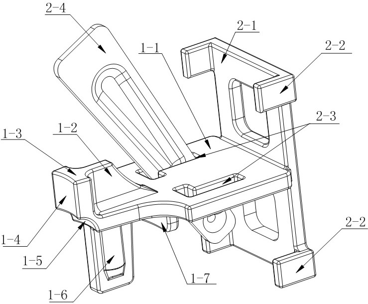
[0044] Insert the wedge pin 2-4, wedge pin 3-4, and the narrow end of wedge pin 5-4 into the L-shaped pin hole 2-3, inverted Ω-shaped pin hole 3-3, and inverted Ω-shaped pin hole 5-3 respectively and keep The upright face is facing the front baffle 2-1, the front baffle 3-1, the front baffle: 5-1, and a bulge is riveted or punched out at the end of the small head, which prevents the wedge pin 2-4 , wedge pin 3-4, wedge pin 5-4 fall off from the pin hole.

[0045] The installation process of one-to-four four-piece suspension frame 2:

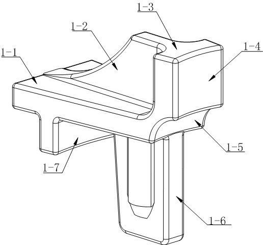
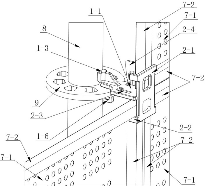
[0046] Such as figure 1 , figure 2 , image 3 As shown, first insert the conjoined pins 1-6 of the integrated lock head 1 of the one-to-four conjoined suspension frame 2 into the jack in the connecting plate 9 of the bu...


PUM


Abstract

The invention provides a disc buckle type overhanging support system. The disc buckle type overhanging support system comprises a lock pin integrated lock head and various connected overhanging supports. The lock pin integrated lock head comprises a main plate, a connected lock head and a connected plug pin, the connected lock head is built on the main plate, the front portion of the connected lock head is a cambered surface part, a knocking platform is arranged in the middle of the connected lock head, a reinforcing rib is arranged on the rear portion of the connected lock head, the connected plug pin is arranged below the main plate, and the tail of the main plate is connected with various cantilever supports; the lock pin integrated lock head is installed on a ring lock type scaffold connecting plate, the load of the connected overhanging support is transmitted to a ring lock type scaffold vertical rod, suspension systems with different overhanging requirements can be formed, and the ring lock type scaffold overhanging support series is firm, practical, convenient to disassemble and assemble, good in application expansibility and long in service life.

Description

technical field [0001] The invention belongs to the field of construction, and in particular relates to a cantilever frame externally connected with a multi-functional extension of a disc buckle scaffold. Background technique [0002] With the popularization of disc-buckled scaffolding and building metal safety nets, structural parts based on connecting discs and external building metal safety nets also need to be developed and designed. At present, they are installed based on fastener-type connectors of vertical poles and horizontal poles. These parts have complex structures, many matching parts, high cost, difficult installation and adjustment, poor positional accuracy, and often interfere with structural parts, which is very inconvenient. For an installation node, one-to-two, one-to-four, and side-by-side installations may occur There are no standard parts to solve the on-site installation problems for complex structures such as the combination of internal and external co...

Claims


Application Information

Patent Timeline
IPC IPC(8): E04G7/06E04G3/18E04G5/00
CPCE04G7/06E04G3/18E04G5/00E04G5/001
Inventor 周波张正江华祖继宏齐小龙张鸿翎李明生
Owner QINGDAO JUNYING EQUIP TECH CO LTD
Learn More