Mechanical equipment fault monitoring equipment and method based on big data

A technology for mechanical equipment and fault monitoring, applied in the field of mechanical equipment fault monitoring equipment based on big data, can solve the problems of dust accumulation in monitoring, affecting monitoring service life, monitoring exposure, etc., to extend service life, facilitate monitoring operations, and achieve protective effect

Pending Publication Date: 2022-04-22
龙春丽
View PDF0 Cites 0 Cited by
  • Summary
  • Abstract
  • Description
  • Claims
  • Application Information

AI Technical Summary

Problems solved by technology

[0003] However, the existing monitors are fixedly installed in the external environment, resulting in exposed monitors. Dust will accumulate on the monitoring surface after long-term use, and dust will affect the service life of the monitor.

Method used


Image

  • Mechanical equipment fault monitoring equipment and method based on big data
  • Mechanical equipment fault monitoring equipment and method based on big data
  • Mechanical equipment fault monitoring equipment and method based on big data

Examples


Embodiment 1

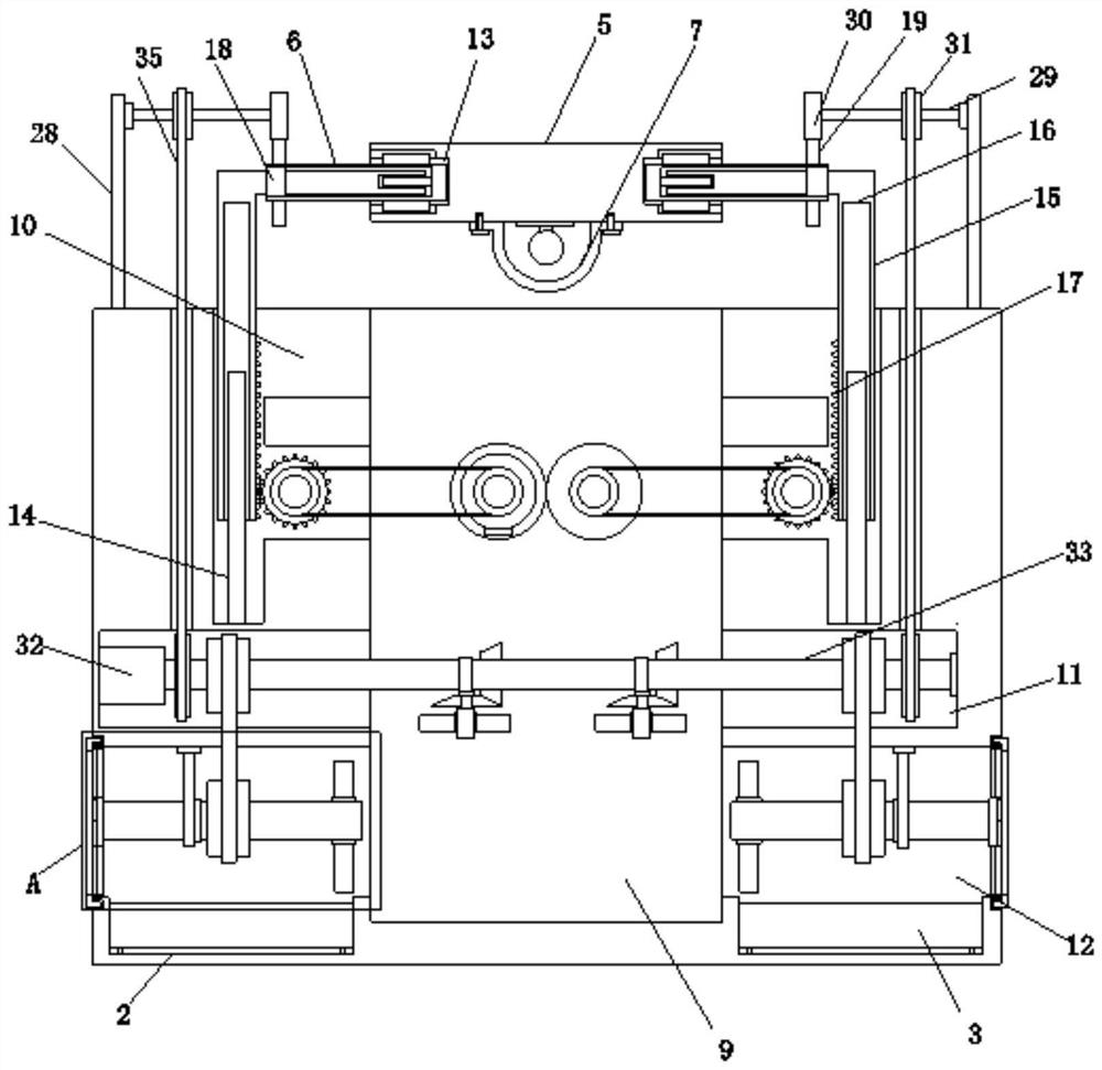
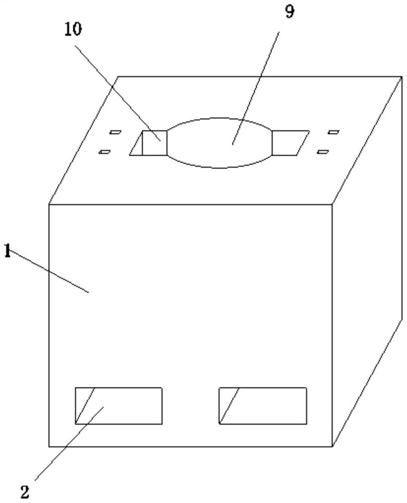
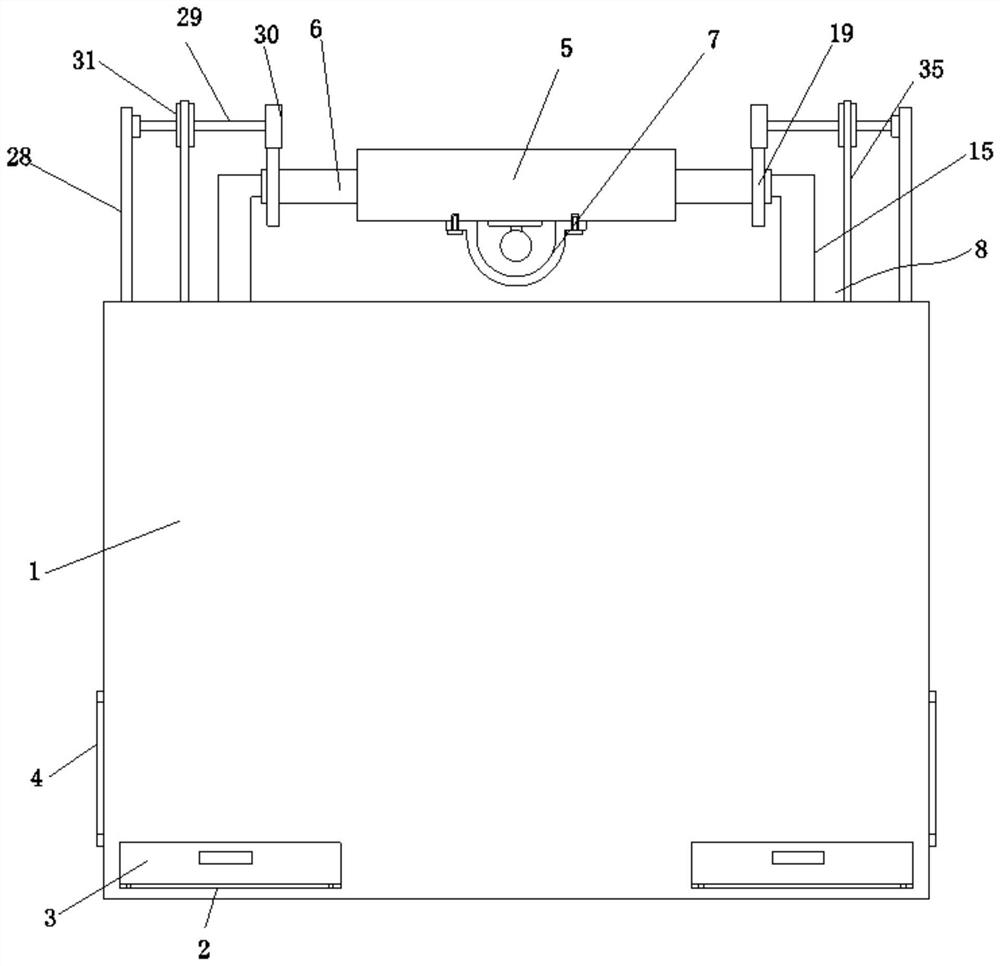
[0048] Embodiment one, by Figure 1 to Figure 8 Given, the present invention comprises placing box body 1 and camera body 7, and the bottom end of the outer side wall of placing box body 1 is provided with placing groove 2 symmetrically, and the interior of placing groove 2 is movably connected with dust storage box 3, and the two sides of placing box body 1 The bottom of the side is symmetrically connected with a filter screen 4, and the top of the housing 1 is provided with a mounting plate 5, and the middle position of the bottom end of the mounting plate 5 is provided with a camera body 7, and both sides of the mounting plate 5 are symmetrically connected with a rotating cylinder 6, two The rotating cylinders 6 are connected by a height adjustment mechanism 8, and the top sides of the storage box 1 are symmetrically provided with rotating auxiliary parts, the inside of the storage box 1 is provided with a storage groove 9, and the storage box 1 is symmetrically provided wit...

Embodiment 2

[0051] Embodiment two, on the basis of embodiment one, by figure 1 and Figure 4 Provide, driver comprises gear six, two rotating shafts one 20, two rotating shafts two 21, motor one 22, four pulleys one 23, two belts one 24 and two gears two 25, two rotating shafts one 20 Installed on the inner wall of the receiving groove 9, two rotating shafts 21 are installed on the inner wall of the groove 10, two rotating shafts one 20 are provided with gear six, and the two gears six are meshingly connected, two rotating shafts one 20 and two rotating shafts one 20 Belt pulley one 23 is all provided with on two rotating shafts 21, and one end of one rotating shaft one 20 is connected with motor one 22 output shafts, and two rotating shafts two 21 are all provided with gear two 25 that are meshed with gear teeth 17, All are connected by belt one 24 between the belt pulley one 23 on the first rotating shaft 20 and the second rotating shaft 21;

[0052] By starting the motor one 22 to ro...

Embodiment 3

[0053] Embodiment three, on the basis of embodiment one, by figure 1 , image 3 , Figure 4 and Figure 5 Given, the rotation aid includes a mounting rod 28, a connecting shaft 29, a third gear 30, a pulley 2 31 and a rotator, the mounting rod 28 is symmetrically installed on the top of the housing 1, and one side of the mounting rod 28 is rotatably connected with a connecting shaft 29, one end of the connecting shaft 29 is provided with a gear three 30 meshed with the gear one 19, and the connecting shaft 29 is provided with a pulley two 31, and the two pulleys two 31 are connected by a rotator, and the rotator includes a through groove, a motor Two 32, rotating shaft 33, belt pulley three 34 and belt two 35, the top of placing casing 1 is symmetrically provided with the through groove that communicates with slot one 11, motor two 32 is installed on the side of slot one 11, motor two The output shaft of 32 is provided with the rotary shaft 33 that is connected with slot on...


PUM


Abstract

The invention relates to the technical field of monitoring, discloses a mechanical equipment fault monitoring device and method based on big data, and solves the problem that the service life of a monitoring device is affected due to the fact that the monitoring device is fixedly installed and placed in an exposed mode, and the monitoring device is easily affected by dust. Placement grooves are symmetrically formed in the bottom end of the outer side wall of the placement box body, dust storage boxes are movably connected into the placement grooves, filter screens are symmetrically connected to the bottoms of the two sides of the placement box body, a mounting plate is arranged above the placement box body, a camera body is arranged in the middle of the bottom end of the mounting plate, and rotating cylinders are symmetrically connected to the two sides of the mounting plate; by arranging the placing box body, the placing groove, the dust storage box, the filter screen, the mounting plate, the rotating cylinder and the camera body, the sealed storage of the camera body can be conveniently realized, the camera body is prevented from being exposed to be influenced by dust, and the service life of the camera body is effectively prolonged.

Description

technical field [0001] The invention belongs to the technical field of monitoring, and specifically relates to a large data-based mechanical equipment failure monitoring device and method. Background technique [0002] There are many types of mechanical equipment. When the mechanical equipment is running, some of its parts and even itself can perform different forms of mechanical movement. The mechanical equipment consists of a driving device, a transmission device, a transmission device, a working device, a braking device, a protective device, a lubrication system, and a cooling system. System and other parts, in industrial production, mechanical equipment failures will occur after long-term use, therefore, it is necessary to monitor mechanical equipment failures. [0003] However, the existing monitors are fixedly installed in the external environment, resulting in exposed monitors, and dust will accumulate on the monitoring surface after long-term use, which will affect t...

Claims


Application Information

Patent Timeline
Patent Type & Authority Applications(China)
IPC IPC(8): F16M11/24F16M11/10F16M11/18H04N5/225B08B5/02B08B15/04
CPCF16M11/24F16M11/10F16M11/18B08B5/02B08B15/04H04N23/50
Inventor 龙春丽
Owner 龙春丽
Why Eureka
Try Eureka