Covering type energy pile buried pipe heat exchanger structure

An energy pile and heat exchanger technology, which is applied in the field of shrouded energy pile buried pipe heat exchanger structure, can solve the influence of the ultimate stress bearing capacity of the pile body, the change of the surface temperature of the concrete pile body, and the influence of heat exchange performance and heat exchange efficiency. and other problems, to achieve the effect of small energy loss, improved pile stress, and increased stroke.

Pending Publication Date: 2022-04-22
CHINA UNIV OF MINING & TECH
View PDF11 Cites 1 Cited by
  • Summary
  • Abstract
  • Description
  • Claims
  • Application Information

AI Technical Summary

Problems solved by technology

[0003] However, the traditional energy piles that are often used at present, because the current energy pile technology is not mature enough, there are often serious heat pipes between the water inlet and outlet pipes, which affects its heat transfer performance and heat transfer efficiency
At the same time, the traditional U-shaped tube directly exchanges heat with the pile body, which will inevitably cause a sharp change in the temperature of the concrete pile body surface, which will affect the pile body stress, pile side friction, pile top settlement and pile limit. impact on bearing capacity

Method used


Image

  • Covering type energy pile buried pipe heat exchanger structure
  • Covering type energy pile buried pipe heat exchanger structure
  • Covering type energy pile buried pipe heat exchanger structure

Examples


Embodiment Construction

[0023] The following will clearly and completely describe the technical solutions in the embodiments of the present invention with reference to the accompanying drawings in the embodiments of the present invention. Obviously, the described embodiments are only some, not all, embodiments of the present invention. Based on the embodiments of the present invention, all other embodiments obtained by persons of ordinary skill in the art without making creative efforts belong to the protection scope of the present invention.

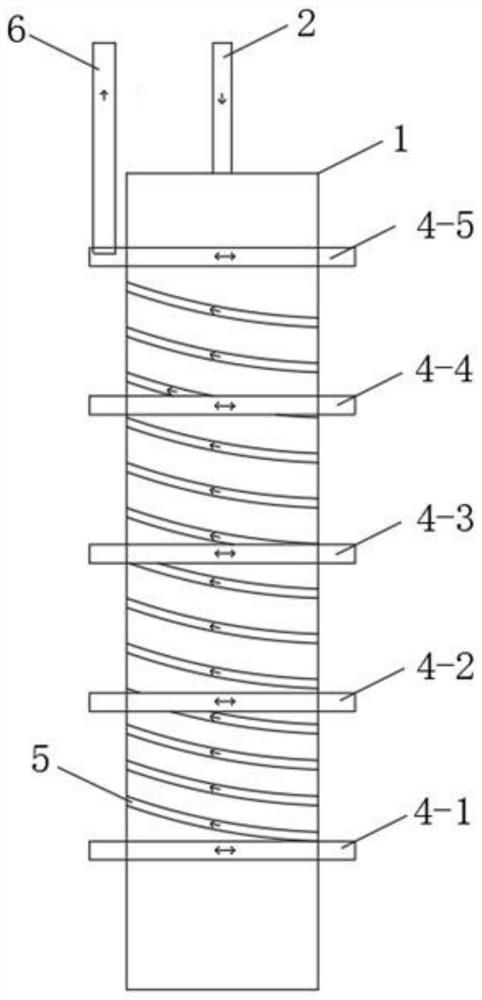
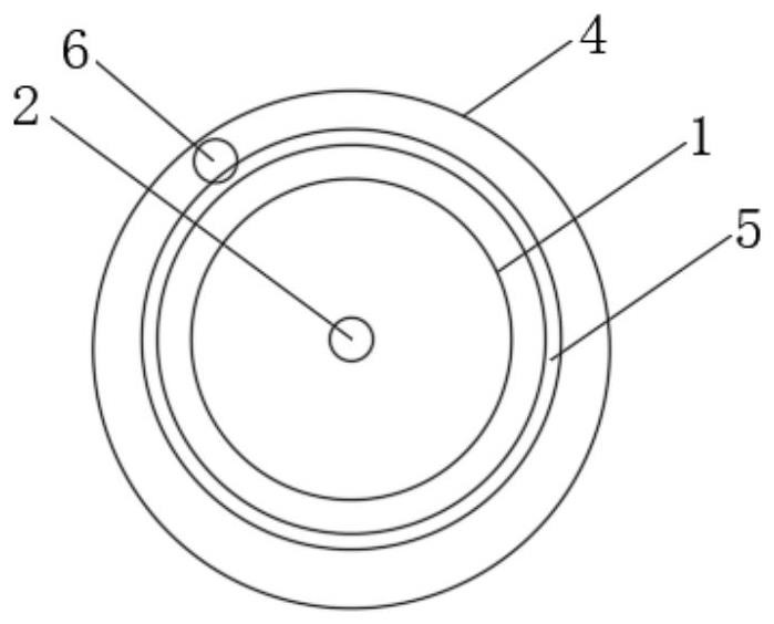
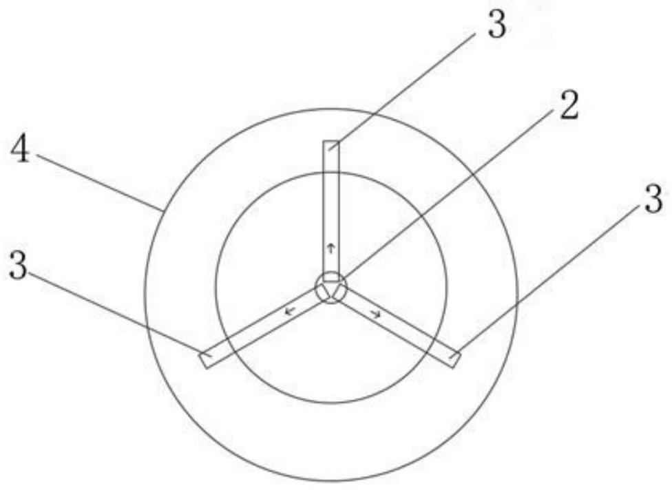
[0024] Such as Figure 1 to Figure 3 As shown, a shrouded energy pile buried pipe heat exchanger structure includes a concrete pile body 1 and a piping system, and the piping system includes a water inlet pipe 2 arranged in the concrete pile body 1 and 5 pipes evenly distributed in the concrete pile body. The outer circular tube 4 on the periphery of the pile body 1, the outer circular tube 4 is annularly closed, the uppermost outer circular tube 4 is close to...


PUM


Abstract

The invention discloses a covering type energy pile buried pipe heat exchanger structure which comprises a concrete pile body and a pipeline system, and the pipeline system comprises a water inlet pipe arranged in the concrete pile body and a plurality of outer circular pipes fixed to the periphery of the concrete pile body in an embedded mode. A plurality of inner connecting pipes are communicated between the bottom of the water inlet pipe and the outer circular pipe at the lowermost end of the concrete pile body, a spiral heat exchange pipe is communicated between every two adjacent outer circular pipes, the spiral heat exchange pipes are embedded in the periphery of the concrete pile body, and the spiral directions of all the spiral heat exchange pipes are the same; the outer circular pipe arranged at the uppermost end is also communicated with a water outlet pipe; according to the structure, the heat exchange performance and heat exchange efficiency of the energy pile can be improved, and the pile body stress, the pile side friction force, the pile top settlement and the ultimate bearing capacity of the pile are improved by reducing the temperature change of the surface of the concrete pile body; and the spiral heat exchange pipe is arranged outside the concrete pile body, so that the flowing distance of cold (hot) water in the pipe is increased, and the heat exchange performance and the heat exchange efficiency of the energy pile are improved.

Description

technical field [0001] The invention relates to the field of ground source heat pump air conditioning technology and soil source heat storage technology, in particular to a shrouded energy pile buried tube heat exchanger structure. Background technique [0002] Energy pile is a building energy-saving technology that utilizes shallow geothermal heat, and the underground heat exchanger of the traditional ground source heat pump system is embedded in the pile foundation. Compared with the traditional vertical borehole buried pipe method, the pile buried pipe ground source heat pump system makes full use of the area of ​​the building itself, does not generate unnecessary additional area, and exchanges heat with the surrounding earth through the concrete pile foundation The material, because it saves part of the drilling process, saves costs, is more convenient, reduces contact thermal resistance, and strengthens the heat transfer between the buried pipe and the soil. At present,...

Claims


Application Information

Patent Timeline
Patent Type & Authority Applications(China)
IPC IPC(8): F24T10/15E02D5/30
CPCF24T10/15E02D5/30F24T2010/53Y02E10/10
Inventor 高蓬辉程昊天温婷予
Owner CHINA UNIV OF MINING & TECH
Why Eureka
Try Eureka