Multi-radar running state real-time monitoring system and monitoring method thereof

A technology for real-time monitoring of operating status, applied in transmission systems, digital transmission systems, radio wave measurement systems, etc., can solve the problems of radar real-time monitoring, information back-check radar function abnormality judgment, failure to meet factory quantities, and inconvenient expansion, etc. problem, to achieve the effect of improving factory yield, improving test efficiency, and facilitating expansion

Pending Publication Date: 2022-04-22
SHENZHEN EAI TECH CO LTD
View PDF7 Cites 0 Cited by
  • Summary
  • Abstract
  • Description
  • Claims
  • Application Information

AI Technical Summary

Problems solved by technology

[0002] In the existing technology, when performing performance tests and stress tests on lidar, one or more lidars are often connected through one device terminal, and the number of lidar devices that can be measured at one time depends on the number of interfaces provided by the device terminal, which is inconvenient Expansion; secondly, when the existing technology performs each operation, it is necessary to reconfirm each test laser radar port number (such as serial port number, etc.), and obtain the laser radar operating status and send control instructions according to the port number, the operation is cumbersome, resulting in inability to Real-time monitoring, information check and radar function abnormality judgment are carried out for each radar, which cannot meet the needs of the factory.

Method used


Image

  • Multi-radar running state real-time monitoring system and monitoring method thereof
  • Multi-radar running state real-time monitoring system and monitoring method thereof

Examples


Embodiment Construction

[0030] The terms "first", "second", "third" and "fourth" in the specification, claims and drawings of the present invention are used to distinguish different objects, rather than to describe a specific order. Furthermore, the terms "include" and "have", as well as any variations thereof, are intended to cover a non-exclusive inclusion. For example, a process, method, system, product or device comprising a series of steps or units is not limited to the listed steps or units, but optionally also includes unlisted steps or units, or optionally further includes For other steps or units inherent in these processes, methods, products or apparatuses.

[0031] Reference herein to an "embodiment" means that a particular feature, structure, or characteristic described in connection with the embodiment can be included in at least one embodiment of the present invention. The occurrences of this phrase in various places in the specification are not necessarily all referring to the same em...


PUM


Abstract

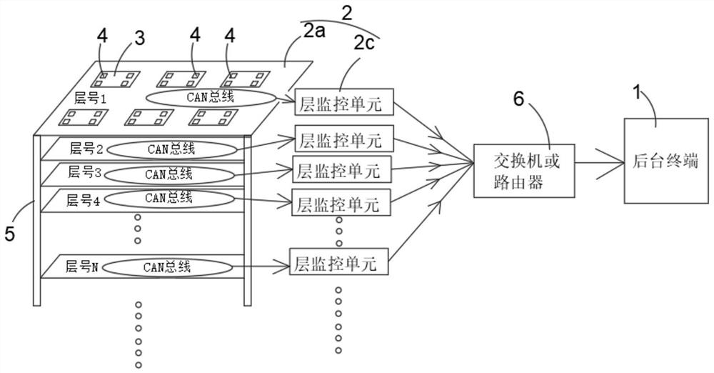
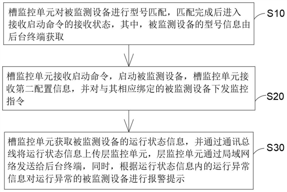
The invention relates to a multi-radar running state real-time monitoring system and a monitoring method thereof. The system comprises a background terminal, a laminate module and a trough plate module, the plurality of trough plate modules are sequentially connected through a communication bus and then are in communication connection with the laminate module, the trough plate modules are in communication connection with a plurality of trough monitoring units, and the trough monitoring units are hung on the communication bus; the layer plate module comprises a layer plate body and a layer monitoring unit, and the layer monitoring unit is used for acquiring operation state information of monitored equipment and uploading the operation state information to the layer monitoring unit; the layer monitoring unit is used for gathering the running state information uploaded by each slot monitoring unit and uploading the running state information to the background terminal; the operation state information comprises operation abnormal information, and when the background terminal receives the operation state information, the operation abnormal information is stored and visually processed and displayed to a user, so that real-time monitoring, information reverse checking and radar function abnormity judgment are carried out on each radar, expansion is more convenient, and the method is not limited by the number of terminal ports.

Description

technical field [0001] The invention relates to the technical field of radar performance testing, in particular to a real-time monitoring system and a monitoring method for multi-radar operating states. Background technique [0002] In the existing technology, when performing performance tests and stress tests on lidar, one or more lidars are often connected through one device terminal, and the number of lidar devices that can be measured at one time depends on the number of interfaces provided by the device terminal, which is inconvenient Expansion; secondly, when the existing technology performs each operation, it is necessary to reconfirm each test laser radar port number (such as serial port number, etc.), and obtain the laser radar operating status and send control instructions according to the port number, the operation is cumbersome, resulting in inability to Real-time monitoring, information check and radar function abnormality judgment for each radar cannot meet the...

Claims


Application Information

Patent Timeline
Patent Type & Authority Applications(China)
IPC IPC(8): G01S7/497H04L12/40
CPCG01S7/497H04L12/40H04L2012/40215
Inventor 褚满京王品
Owner SHENZHEN EAI TECH CO LTD
Why Eureka
Try Eureka