Direct-drop type rectifying and voltage-regulating transformer and manufacturing method thereof

A voltage regulating transformer and transformer technology, applied in the field of transformers, can solve the problems of inconvenient transportation, large drop-down transformers, and excessive weight of drop-down transformers, and achieve the effect of dispersing weight and facilitating transportation.

Inactive Publication Date: 2022-04-22
佛山市兴智达电子有限公司
View PDF0 Cites 1 Cited by
  • Summary
  • Abstract
  • Description
  • Claims
  • Application Information

AI Technical Summary

Problems solved by technology

[0007] The purpose of the present invention is to provide a direct-drop rectifying voltage-regulating transformer and its manufacturing method, which has the advantages of splitting the transformer, effectively dispersing the weight of the transformer, and facilitating transportation, and solves the problem that the direct-drop transformer is relatively large, which leads to It is troublesome to transport the drop-down transformer, and it is inconvenient to transport due to the heavy weight of the drop-down transformer during transportation

Method used


Image

  • Direct-drop type rectifying and voltage-regulating transformer and manufacturing method thereof
  • Direct-drop type rectifying and voltage-regulating transformer and manufacturing method thereof
  • Direct-drop type rectifying and voltage-regulating transformer and manufacturing method thereof

Examples


Embodiment 1

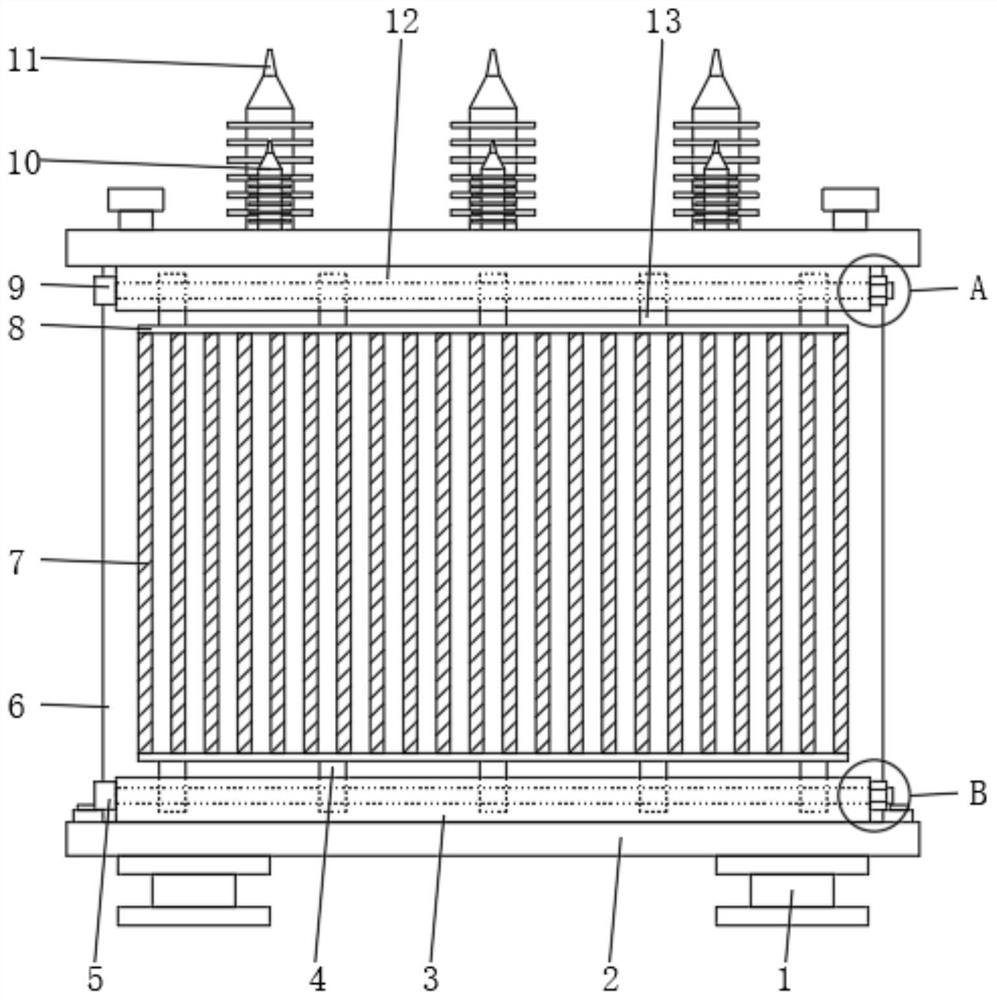
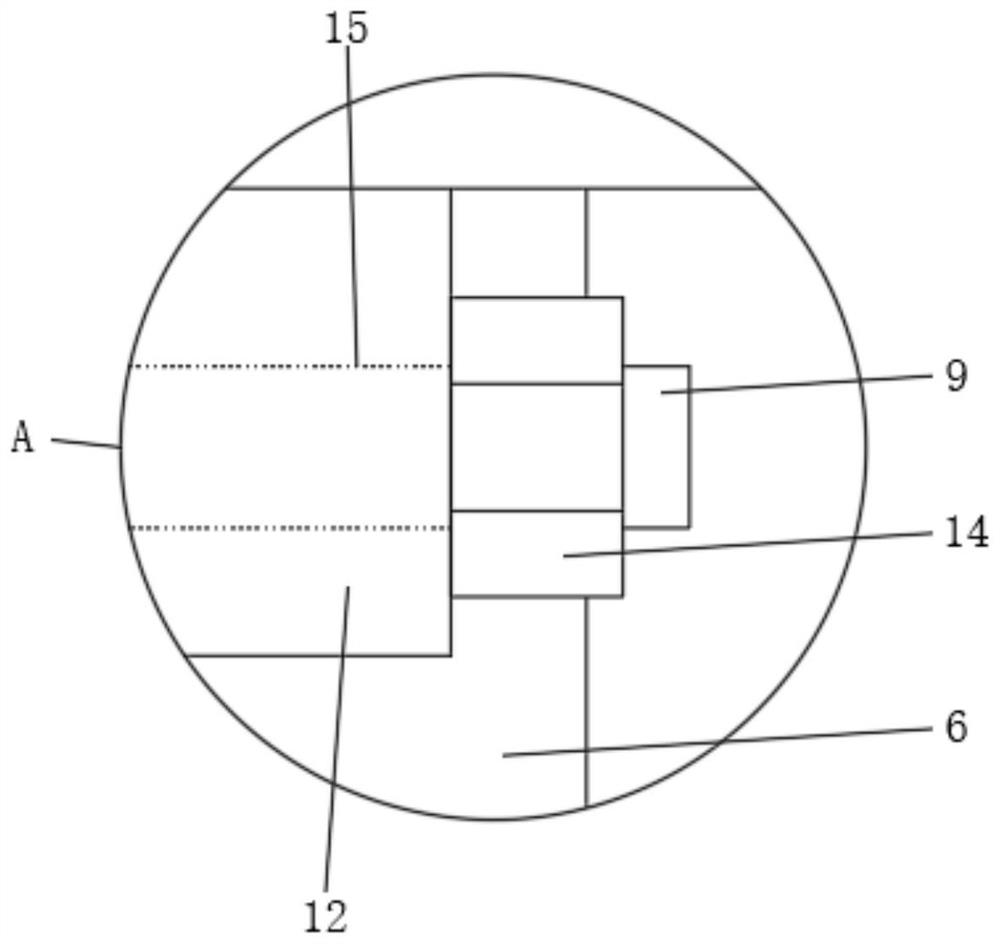
[0039] see figure 1 , Figure 4 and Figure 6 , an embodiment provided by the present invention: a direct-drop rectifying voltage regulating transformer, including a base 2, a first stud 5, a transformer body 6, a heat sink 7 and a second stud 9, and the front end of the upper surface of the transformer body 6 Three low-voltage bushings 10 are fixed equidistantly, and three high-voltage bushings 11 are fixed equidistantly on the rear end of the upper surface of the transformer body 6 . The tops of the front and rear ends of the transformer body 6 are respectively welded with second positioning plates 12, the bottoms of the opposite sides of the two second positioning plates 12 are respectively provided with second slots 22, and the two second positioning plates 12 are respectively provided with a second positioning plate 12. Two through holes 15, the bottoms on both sides of the transformer body 6 are respectively welded with fixing strips 18.

Embodiment 2

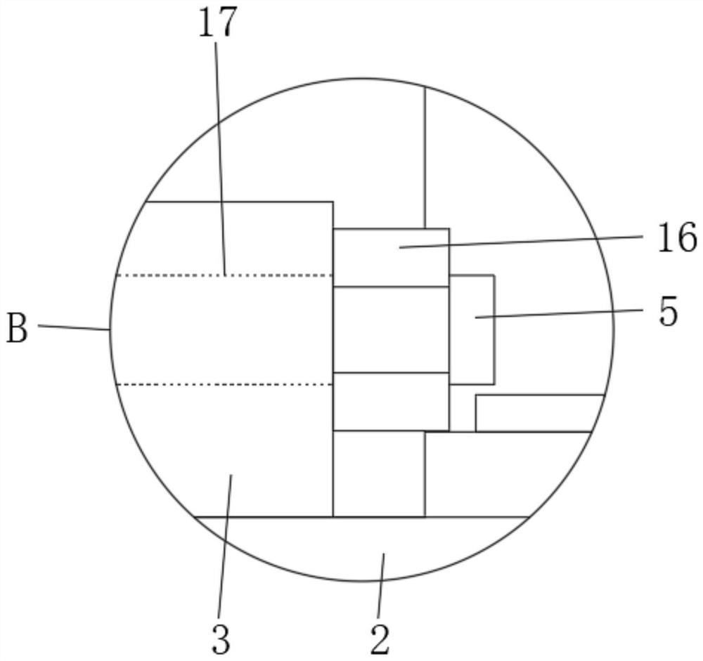
[0041] see figure 1 and Figure 5 , an embodiment provided by the present invention: a direct-drop rectifying voltage regulating transformer, I-shaped feet 1 are respectively welded on both sides of the bottom end of the base 2, and the two I-shaped feet 1 are symmetrical to the central axis of the bottom end of the base 2 distributed. The front and rear ends of the upper surface of the base 2 are respectively welded with a first positioning plate 3, and the tops of the opposite sides of the two first positioning plates 3 are respectively provided with a first slot 20, and the two first positioning plates 3 are respectively provided with a first positioning plate 3. A through hole 17 .

Embodiment 3

[0043] see Figure 1 to Figure 4 , an embodiment provided by the present invention: a direct-drop rectifying voltage regulating transformer, the upper and lower ends of the heat sink 7 are respectively welded with a connecting plate 8, and the lower surface of the connecting plate 8 at the bottom of the heat sink 7 is welded with a first plug-in plate 4. The upper surface of the connecting plate 8 on the top of the heat sink 7 is welded with a second plug-in plate 13 .

[0044] The second inserting plate 13 is inserted into the second slot 22 correspondingly, the second stud 9 passes through the second inserting plate 13 and the second positioning plate 12 from the second through hole 15, and one end of the second stud 9 is threadedly mounted with The second fastening nut 14, the bottom end of the transformer body 6 is installed on the upper surface of the base 2 between the two first positioning plates 3, the fixing bar 18 fixing bolts 19 are fixed with the base 2, and the fr...


PUM


Abstract

The direct-drop type rectifying and voltage-regulating transformer comprises a base, a first stud, a transformer body, cooling fins and second studs, second positioning plates are welded to the tops of the front end face and the rear end face of the transformer body correspondingly, and second inserting grooves are formed in the bottoms of the opposite sides of the two second positioning plates correspondingly; fixing strips are welded to the bottoms of the two sides of the transformer body respectively. I-shaped bottom feet are welded to the two sides of the bottom end of the base correspondingly, first positioning plates are welded to the front end and the rear end of the upper surface of the base correspondingly, and first inserting grooves are formed in the tops of the opposite sides of the two first positioning plates correspondingly; connecting plates are welded to the upper ends and the lower ends of the cooling fins correspondingly, first inserting plates are welded to the lower surfaces of the connecting plates at the bottoms of the cooling fins, and second inserting plates are welded to the upper surfaces of the connecting plates at the tops of the cooling fins. The transformer has the advantages that the transformer is split, the weight of the transformer is effectively dispersed, and transportation is convenient.

Description

technical field [0001] The invention relates to the technical field of transformers, in particular to a direct-drop rectifying voltage regulating transformer and a manufacturing method thereof. Background technique [0002] The transformer is a device that uses the principle of electromagnetic induction to change the AC voltage. The main components are the primary coil, the secondary coil and the iron core (magnetic core). The main functions are: voltage conversion, current conversion, impedance conversion, isolation, voltage stabilization (magnetic saturation transformer), etc. [0003] Transformers can be divided into: distribution transformers, power transformers, fully sealed transformers, combined transformers, dry-type transformers, oil-immersed transformers, single-phase transformers, electric furnace transformers, rectifier transformers, reactors, anti-interference transformers, lightning protection Transformers, box-type transformer test transformers, corner transf...

Claims


Application Information

Patent Timeline
Patent Type & Authority Applications(China)
IPC IPC(8): H01F27/02H01F27/06H01F41/00
CPCH01F27/06H01F27/022H01F27/025H01F41/00
Inventor 邱启辉
Owner 佛山市兴智达电子有限公司
Why Eureka
Try Eureka