Transfer device for wafer conveying

A transfer device and wafer technology, applied in the field of polishing, can solve the problem that two wafers cannot be transferred and transported at the same time, and achieve the effects of improving stability and efficiency, flexible application, and easy installation

Pending Publication Date: 2022-04-22
BEIJING SEMICORE PRECISION MICROELECTRONICS EQUIP CO LTD
View PDF0 Cites 0 Cited by
  • Summary
  • Abstract
  • Description
  • Claims
  • Application Information

AI Technical Summary

Problems solved by technology

[0005] Therefore, the technical problem to be solved by the present invention is to overcome the defect that the wafer transfer table in the prior art cannot transfer and transfer two wafers at the same time, thereby providing a transfer device for wafer transfer

Method used


Image

  • Transfer device for wafer conveying
  • Transfer device for wafer conveying
  • Transfer device for wafer conveying

Examples


Embodiment Construction

[0038] The technical solutions of the present invention will be clearly and completely described below in conjunction with the accompanying drawings. Apparently, the described embodiments are some of the embodiments of the present invention, but not all of them. Based on the embodiments of the present invention, all other embodiments obtained by persons of ordinary skill in the art without making creative efforts belong to the protection scope of the present invention.

[0039] In the description of the present invention, it should be noted that the terms "center", "upper", "lower", "left", "right", "vertical", "horizontal", "inner", "outer" etc. The indicated orientation or positional relationship is based on the orientation or positional relationship shown in the drawings, and is only for the convenience of describing the present invention and simplifying the description, rather than indicating or implying that the referred device or element must have a specific orientation, ...


PUM


Abstract

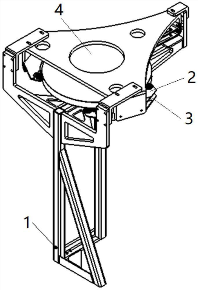
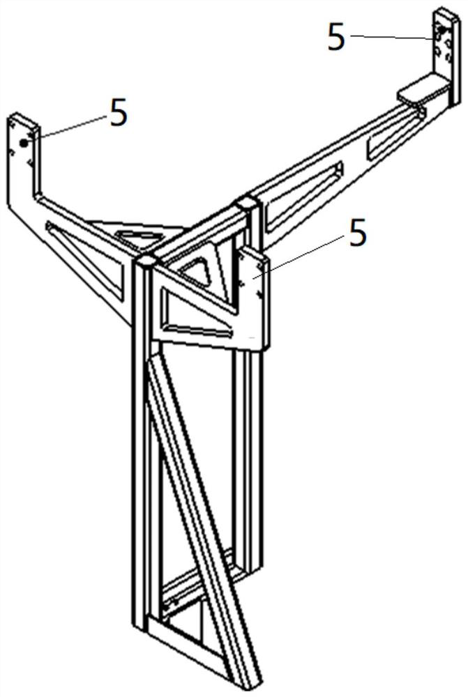
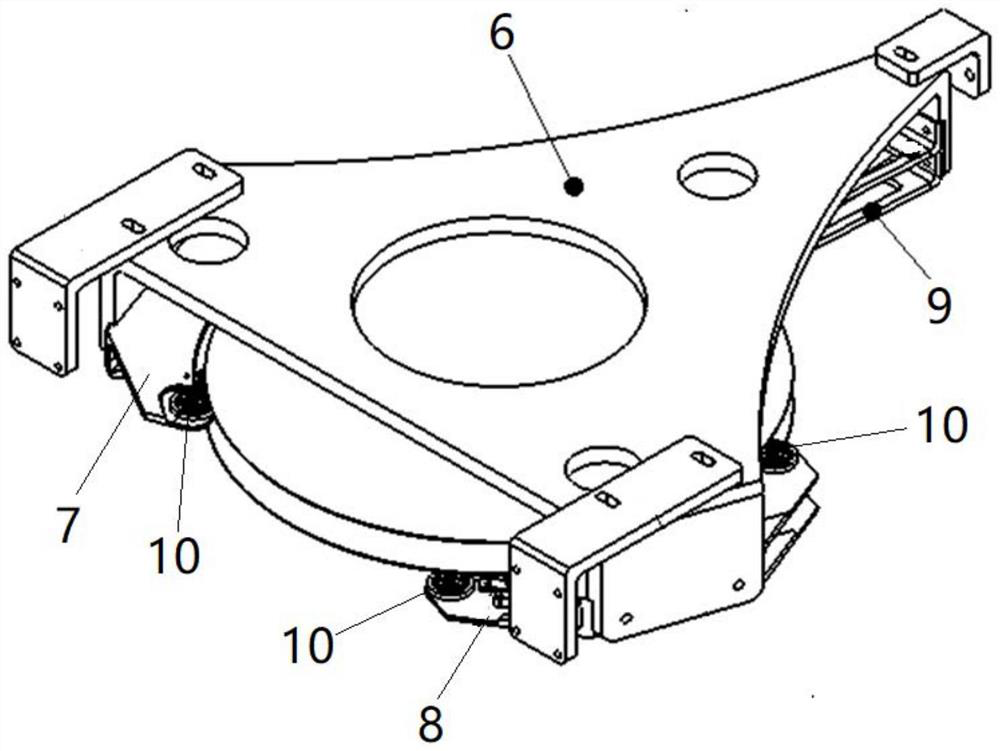
The invention provides a transfer device for wafer conveying. The transfer device is characterized in that the top of a support frame is provided with an accommodating space for limiting up-down passage of wafers; a first slide holder and a second slide holder which are used for bearing wafers are arranged in the accommodating space, and the first slide holder and the second slide holder are arranged at an interval up and down; conveying ports suitable for horizontal passing of wafers are formed in the containing space in the circumferential direction and comprise the first conveying port used for facing the first polishing and cleaning system, the second conveying port used for facing the second polishing and cleaning system and the third conveying port used for facing the EFEM. According to the invention, the accommodation space limits the up-and-down passage of the wafer, and the three conveying ports in the circumferential direction of the accommodation space limit the conveying path of the wafer; the first slide holder and the second slide holder which are arranged at an interval up and down are provided with conveying ports which are in butt joint with each other; and the two layers of wafers which are spaced up and down can be independently transferred and operated through the respective corresponding conveying ports so as to be matched with two parallel systems to operate at the same time.

Description

technical field [0001] The invention relates to the technical field of polishing, in particular to a transfer device for wafer transportation. Background technique [0002] The chemical mechanical polishing planarization equipment usually includes a semiconductor equipment front-end module (EFEM), a polishing system and a cleaning system, and both the wafer to be polished and the polished wafer are placed in the semiconductor equipment front-end module (EFEM). [0003] At present, the wafer transfer is realized by the wafer transfer table and the manipulator. The wafer transfer table mainly cooperates with the manipulator to complete the sending and receiving of the wafer; when the wafer is polished, the wafer to be polished is passed through the front-end module of the equipment ( EFEM), the wafer exchange mechanism is transported to the polishing system; after the wafer is polished, the polished wafer needs to be returned to the cleaning system, and finally transported to ...

Claims


Application Information

Patent Timeline
Patent Type & Authority Applications(China)
IPC IPC(8): H01L21/677B24B37/34H01L21/67H01L21/687
CPCH01L21/67742H01L21/68721H01L21/67276B24B37/345
Inventor 李伟陶利权史霄
Owner BEIJING SEMICORE PRECISION MICROELECTRONICS EQUIP CO LTD
Why Eureka
Try Eureka