Blade assembling equipment

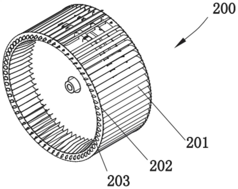
A blade assembly and equipment technology, applied in metal processing equipment, other manufacturing equipment/tools, metal processing, etc., can solve the problems of corrosion, low efficiency, easy damage to the impeller 200, etc., achieve stable bending quality, avoid later corrosion, The effect of quick bending

Pending Publication Date: 2022-04-26
湖南创研智能装备有限公司
View PDF9 Cites 4 Cited by
  • Summary
  • Abstract
  • Description
  • Claims
  • Application Information

AI Technical Summary

Problems solved by technology

[0003] At present, in most cases, the manual bending method is used, which is easy to damage the impeller 200, which will cause later corrosion. At the same time, the efficiency is relatively low, and it is difficult to ensure the quality of the bending

Method used


Image

  • Blade assembling equipment
  • Blade assembling equipment
  • Blade assembling equipment

Examples


Embodiment Construction

[0027] In order to facilitate the understanding of the present invention, the present invention will be described in more detail below in conjunction with the accompanying drawings and preferred embodiments, but the protection scope of the present invention is not limited to the following specific embodiments.

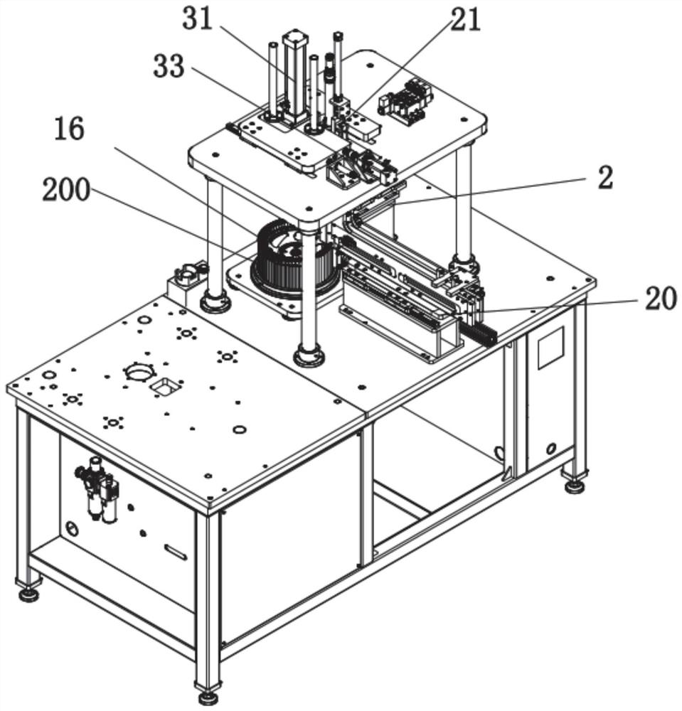
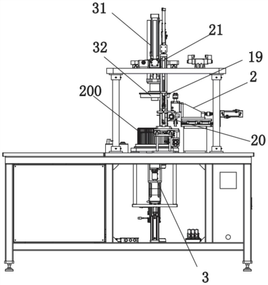
[0028] Such as Figure 2-6 As shown, the embodiment of the present invention discloses a blade assembly equipment, including a frame 1 and a bending mechanism 2 installed on the frame 1, a rotating mechanism 3, an impeller positioning mechanism 4 and a blade 201 for positioning the impeller. The assembly mechanism 19 of mechanism 4, the rotating mechanism 3 is a rotating motor, which is installed on the bottom of the impeller positioning mechanism 4, and the rotating shaft of the rotating motor is rotationally connected with the impeller positioning mechanism 4 through a coupling. The impeller positioning mechanism 4 is rotated and installed on the rotating mechanism 3...


PUM


Abstract

The invention discloses blade assembling equipment which comprises a rack, a bending mechanism, a rotating mechanism, an impeller positioning mechanism and an assembling mechanism, the bending mechanism, the rotating mechanism and the impeller positioning mechanism are mounted on the rack, the assembling mechanism is used for assembling a blade into the impeller positioning mechanism, the impeller positioning mechanism is rotatably mounted on the rotating mechanism, and the bending mechanism comprises an up-down telescopic driving part and a bending roller. The bending roller is installed at the telescopic end of the up-down telescopic driving piece so as to roll and bend the tip end of the blade. Automatic feeding and assembling of the blades and rapid bending of the tip ends of the assembled blades can be achieved, after an impeller is installed on the impeller positioning mechanism, the lower telescopic driving piece enables the bending roller to abut against an end plate of the impeller, the impeller positioning mechanism is driven by the rotating mechanism to drive the blade to be bent, and the blade tip ends can be bent rapidly. Furthermore, the bending roller rolls while bending the tip of the blade and flattening the tip on the end plate, so that the tip of the blade can be quickly bent, and the bending quality is stable.

Description

technical field [0001] The invention relates to the field of welding tooling technology, in particular to blade assembly equipment. Background technique [0002] The impeller 200 (also known as the air duct impeller) of the range hood includes end plates 202 and blades 201 arranged in parallel up and down, see the attached figure 1 , the upper and lower ends of the blade 201 are connected to the end plate 202 . Specifically, during the assembly process, it is necessary to insert the blade tips 203 at both ends of the blade 201 into the holes of the end plate 202, and then bend and flatten the blade tips 203 protruding from the holes of the end plate 202 to fix the blade 201. . [0003] At present, manual bending is used in most cases, which is easy to damage the impeller 200 , and then cause later corrosion, while the efficiency is relatively low, and it is difficult to ensure the quality of bending. Contents of the invention [0004] The technical problem to be solved ...

Claims


Application Information

Patent Timeline
Patent Type & Authority Applications(China)
IPC IPC(8): B23P23/04B21D19/04B23P19/04
CPCB23P23/04B21D19/04B23P19/04
Inventor 张人斌
Owner 湖南创研智能装备有限公司
Why Eureka
Try Eureka