
Novel waste conveying belt protection device and waste conveying device

A transport belt and protection device technology is applied in the field of new waste transport belt protection device and waste transport device, which can solve problems such as easy jamming of equipment and easy damage to belts, achieve safe operation, simplify manufacturing and replacement, and save equipment maintenance cost effect

Pending Publication Date: 2022-04-26
武汉宝熠德工程技术有限公司
View PDF0 Cites 0 Cited by
  • Summary
  • Abstract
  • Description
  • Claims
  • Application Information

AI Technical Summary

Problems solved by technology

[0006] This application provides a new waste transport belt protection device and waste transport device to solve the problem that the belt is easily damaged or the equipment is easily jammed in the prior art

Method used


Image

  • Novel waste conveying belt protection device and waste conveying device
  • Novel waste conveying belt protection device and waste conveying device
  • Novel waste conveying belt protection device and waste conveying device

Examples


Embodiment 1

[0048] In a possible embodiment, such as Figure 4 with Figure 5 As shown, the first adjacent surface formed by two adjacent pallet units 100 includes a first plane 201 and a second plane 202, and the first plane 201 and the second plane 202 are alternately arranged to form the adjacent surface 200 , the first plane 201 and the second plane 202 are perpendicular, and one of the first plane 201 or the second plane 202 is consistent with the belt movement direction. In this embodiment, this kind of pallet unit is easy to process, and a certain structural strength can be achieved by setting the lengths of the first plane 201 and the second plane 202. In consideration of reducing the total length of the gap, in the figure The length of the second plane consistent with the belt movement direction should be set shorter, for example, the length ratio of the first plane to the second plane is preferably 4:1-10:1.

Embodiment 2

[0050] In another feasible embodiment, such as Image 6 As shown, the first adjacent surface formed by two adjacent pallet units 100 includes a first plane 201 and a second plane 202, and the first plane 201 and the second plane 202 are alternately arranged to form the adjacent surface 200 , the first plane 201 and the second plane 202 may be perpendicular, or may form a certain angle, and at the same time, the first plane or the second plane and the belt movement direction also have an angle α. The pallet unit in this embodiment is also easy to process, and according to different usage requirements, the angle value of α can be adjusted correspondingly, which is more flexible.

Embodiment 3

[0052] In yet another feasible embodiment, such as Figure 7 As shown, the difference from the second embodiment is that in this embodiment, the angle α is changed from the acute angle in the second embodiment to an obtuse angle, so the shape of the contact surface is also changed from a triangle to a trapezoidal structure. This slightly increases the difficulty, but further reduces the chances of strip scrap corners getting inserted into the gaps.

[0053] It can be known from the first to third embodiments above that the included angle between the first plane 201 and the second plane 202 can be selected within the range of 0° to 180°, which is more flexible.


PUM


Abstract

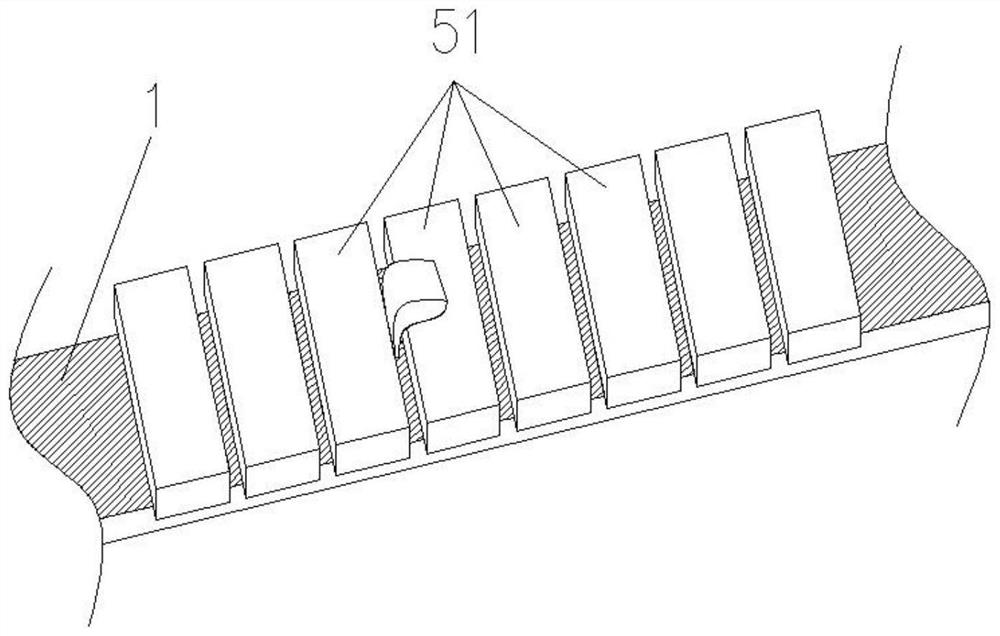
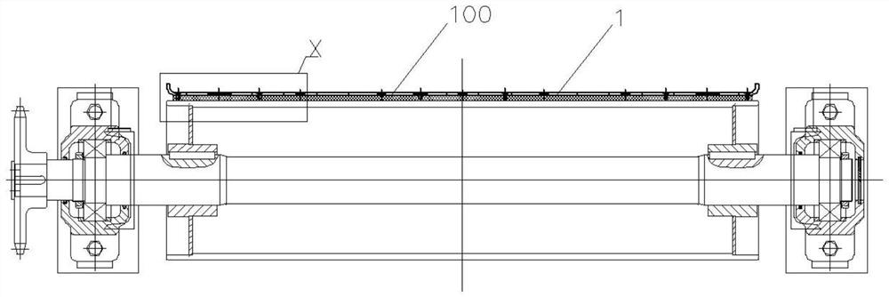
The invention discloses a novel waste conveying belt protection device and a waste conveying device. The novel waste conveying belt protection device comprises a protection supporting plate assembly fixed to the outer surface of a waste conveying belt. The protective supporting plate assembly is formed by a plurality of adjacent supporting plate units with the same shape; the adjacent surfaces of any two supporting plate units are formed by connecting at least two first adjacent surfaces which are not in the same plane. According to the scheme, the supporting plate unit is specifically designed, the problem that the belt protection supporting plate is easily inserted into strip steel waste is effectively solved, the safety protection effect of the waste conveying device is remarkably improved, the equipment failure rate is reduced, the production operation efficiency of a unit is improved, and the equipment maintenance cost is saved.

Description

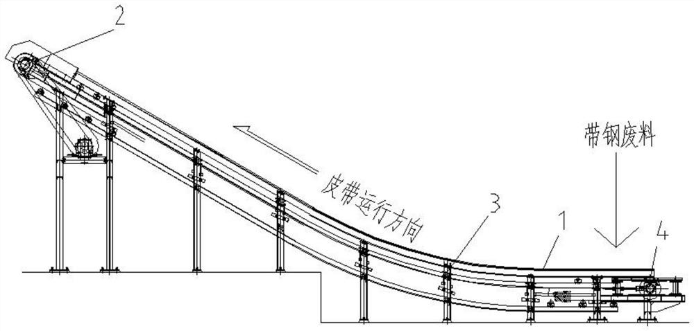
technical field [0001] The invention relates to the technical field of transport equipment, in particular to a novel waste transport belt protection device and a waste transport device. Background technique [0002] In the operation of the cold-rolled strip continuous processing unit, it is usually necessary to cut off the irregular head and tail of the strip during the uncoiling process to meet the production requirements of the subsequent process. The cut strip head and tail scraps are often used by belt conveyors output and collect. [0003] Depend on figure 1 As shown, it is a belt conveyor commonly used in the prior art for transporting strip steel scrap, its structure mainly includes a scrap conveyor belt 1 set at a certain inclination angle, and a belt chain transmission device 2 for driving the scrap conveyor belt 1 to run. For supporting the frame structure 3 of the waste conveyor belt 1, the belt tensioner 4, etc. When in use, strip steel scraps fall from the lo...

Claims


Application Information

Patent Timeline
Patent Type & Authority Applications(China)
IPC IPC(8): B65G15/30
CPCB65G15/30B65G2207/40
Inventor 黄辉
Owner 武汉宝熠德工程技术有限公司
Learn More