
Raw material weighing device for neodymium iron boron rapid hardening sheet production

A technology of sheet production and weighing devices, which is applied in the direction of measuring devices, weighing equipment and applications of materials with special properties/forms, and can solve problems such as manual calculations

Pending Publication Date: 2022-04-26
赣州华京稀土新材料有限公司
View PDF1 Cites 0 Cited by
  • Summary
  • Abstract
  • Description
  • Claims
  • Application Information

AI Technical Summary

Problems solved by technology

[0005] In order to overcome the disadvantage that the existing weighing equipment for the production of NdFeB quick-setting flakes requires manual calculation of the weighing results each time, the purpose of the present invention is to provide a NdFeB quick-setting machine that can quantitatively discharge materials. Raw material weighing device for flake production

Method used


Image

  • Raw material weighing device for neodymium iron boron rapid hardening sheet production
  • Raw material weighing device for neodymium iron boron rapid hardening sheet production
  • Raw material weighing device for neodymium iron boron rapid hardening sheet production

Examples


Embodiment 1

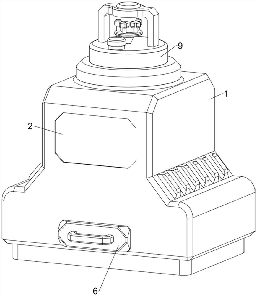
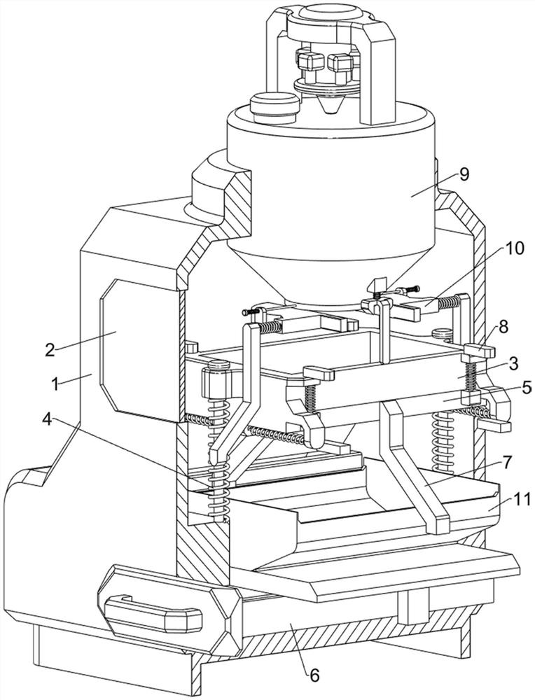
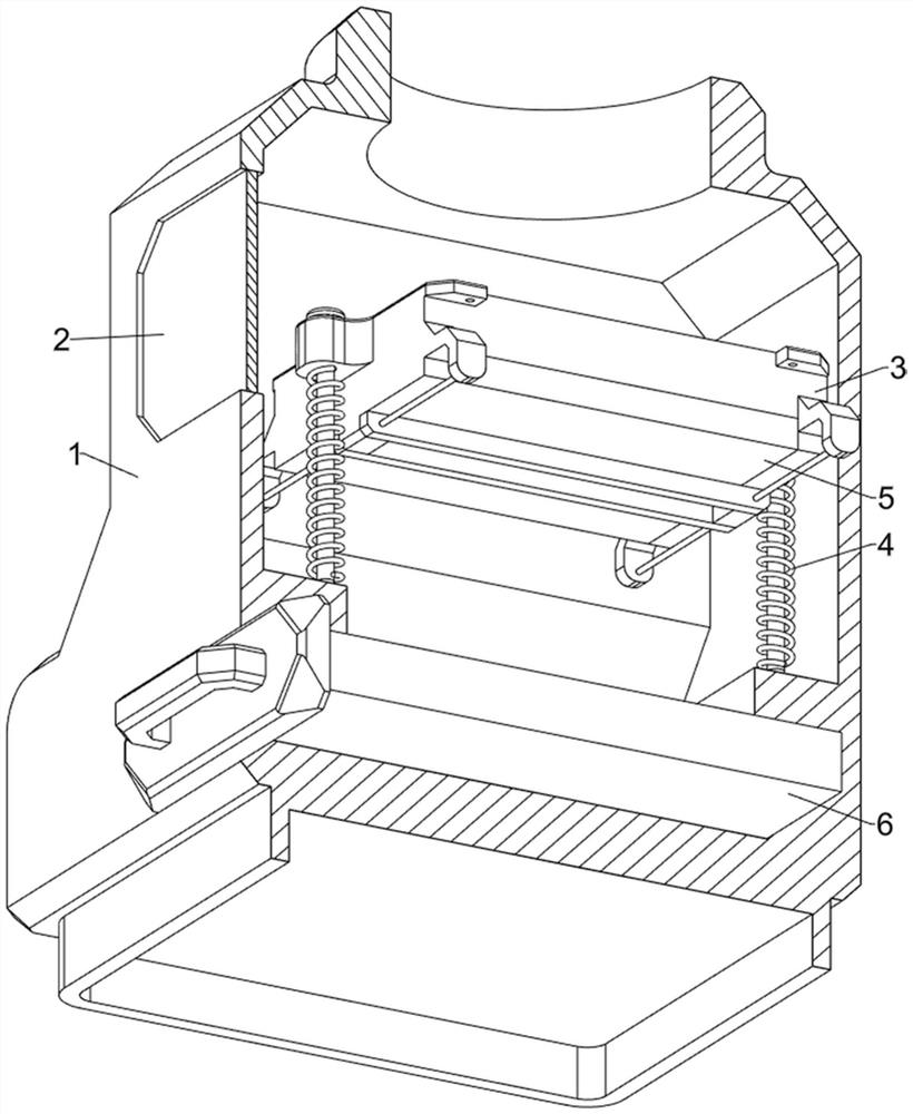
[0037] A raw material weighing device for the production of NdFeB quick-setting flakes, reference Figure 1- Figure 7, including shell 1, observation glass 2, support frame 3, first spring 4, first baffle 5, collection box 6, open component 7 and stuck component 8, the front side of the upper part of the shell 1 is provided with observation glass 2, the inner middle of the shell 1 is provided with a support frame 3, the upper middle of the upper middle of the front and rear sides of the support frame 3 and the upper middle of the shell 1 are equipped with a first spring 4, the lower part of the support frame 3 is symmetrical sliding type with the first baffle 5, when people pour raw material into the support frame 3, the first baffle 5 can block the raw material, Housing 1 in the lower middle sliding type is provided with a collection box 6, when the raw material in the support frame 3 reaches a certain amount, the first baffle 5 will move outward to open, so that the raw material...

Embodiment 2

[0042] On the basis of Example 1, reference Figure 1 、 Figure 2 、 Figure 8 and Figure 9 , also includes a grinding assembly 9, grinding components comprising a storage tank 91, with a hole leak disc 92, a support rod 93, a motor 94, a grinding disc 95 and a dust cover 96, the upper middle of the shell 1 is provided with a storage tank 91, the inner lower part of the storage tank 91 is equipped with a hole leakage plate 92 and connected, the storage tank 91 is welded with a support rod 93, the upper middle of the support rod 93 is bolted to the motor 94, the output shaft of the motor 94 is provided with a grinding disc 95, and the grinding disc 95 is connected to the storage tank 91 rotary connection. The bottom of the grinding disc 95 is in contact with the bottom of the leakage disc 92 with a hole, starting the motor 94, which can drive the grinding disc 95 to rotate, thereby grinding the raw material, the storage tank 91 is placed on the front side of the top cover 96.

[0043]...


PUM


Abstract

The invention relates to a raw material weighing device, in particular to a raw material weighing device for neodymium iron boron rapid hardening sheet production. The invention aims to provide the raw material weighing device for neodymium iron boron rapid hardening sheet production, wherein the raw material weighing device can realize quantitative discharging. The raw material weighing device for neodymium iron boron rapid hardening sheet production comprises a shell, observation glass, a supporting frame, first springs, a first baffle and the like, the observation glass is arranged on the upper portion of the front side of the shell, the supporting frame is arranged in the middle of the inner side of the shell in a sliding mode, and the first springs are arranged between the middles of the upper portions of the front side and the rear side of the supporting frame and the shell. Raw materials are manually poured into a supporting frame, the supporting frame can slowly move downwards, when the raw materials in the supporting frame reach a certain amount, a first baffle can move outwards to be opened, so that the raw materials in the supporting frame fall into a collecting frame, the purpose of quantitative discharging is achieved, manual calculation is not needed every time, and time and labor are saved.

Description

Technical field [0001] The present invention relates to a raw material weighing device, in particular to a raw material weighing device for the production of NdFeB quick-setting flakes. Background [0002] NdFeB quick-setting flakes of raw materials are generally powdered, at present, people are using the spiral measurement method to measure the powdered raw materials, need to consider different environmental conditions, different atmospheric pressure on the detection results of the impact, the process is more troublesome. [0003] Patent application CN209802486U, the publication date is 20191217, discloses a kind of NdFeB rapid-setting flake production of ingredient weighing equipment, comprising a bottom plate, the top of the bottom plate on both sides of the fixed connection is a support leg, the top of the two support legs are fixed with the bottom of the working platform on both sides of the fixed connection, the middle of the working platform is opened with a limited slot,...

Claims


Application Information

Patent Timeline
Patent Type & Authority Applications(China)
IPC IPC(8): G01G17/06B02C7/08B02C7/11
CPCG01G17/06B02C7/08B02C7/11
Inventor 刘光亮郭春荣王珍
Owner 赣州华京稀土新材料有限公司
Learn More