Anti-skid performance detection equipment for track production
A technology of anti-skid performance and testing equipment, which is applied in the direction of vehicle trackless testing, etc., can solve the problems of inconvenient skid adjustment, increase of use cost, etc., and achieve the effect of improving the scope of application
- Summary
- Abstract
- Description
- Claims
- Application Information
AI Technical Summary
Problems solved by technology
Method used
Image
Examples
Embodiment 1
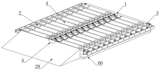
[0036] Embodiment one, by Figure 1 to Figure 11 Provided, the present invention includes anti-skid performance support testing platform 1, the top of anti-skid performance support testing platform 1 is provided with several first rectangular holes 2 and several second rectangular holes 3, the first rectangular holes 2 and the second rectangular holes 3 Rollers 4 are arranged inside, and both ends of the rollers 4 are provided with supporting movable seats 5, and the two ends of the rollers 4 are respectively fixedly connected with a first fixed shaft 6 and a second fixed shaft 7, and the first fixed shaft 6 and the The second fixed shaft 7 runs through the corresponding supporting movable seat 5 respectively, and the first fixed shaft 6 and the second fixed shaft 7 are respectively connected with the corresponding supporting movable seat 5 through the first bearing 8. Both sides of the first rectangular hole 2 Both sides inner walls of the inner wall and the second rectangula...
Embodiment 2
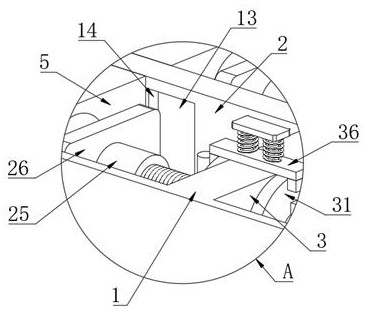
[0038] Embodiment two, on the basis of embodiment one, by figure 1 , figure 2 and Figure 10 It is given that the thread anisotropic adjustment unit includes a fixed column 25 arranged at one end of the first fixed shaft 6, one end of the fixed column 25 is provided with a thread groove 12 matching with the rotating bidirectional adjustment screw 10, and one side of the fixed column 25 is provided with There is a first movable adjustment plate 26, a second through hole 27 is opened on one side of the first movable adjustment plate 26, the fixed column 25 runs through the second through hole 27, and the inner wall of the fixed column 25 and the second through hole 27 is fixedly connected, One end of the first movable adjusting plate 26 is connected with the side supporting the movable seat 5 through two supporting columns 28;
[0039] According to the distance between the two crawlers, the two-way adjusting screw rod 10 is driven to rotate, and through the cooperation of the...
Embodiment 3
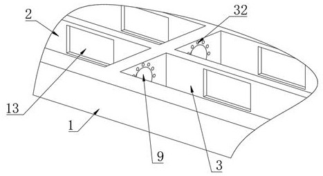
[0040] Embodiment three, on the basis of embodiment one, by figure 1 , figure 2 , image 3 , Figure 7 and Figure 8It is given that two movable limit anti-rotation rings 31 are sheathed on the outside of the rotating bidirectional adjusting screw 10, and a plurality of first limit grooves 32 are provided on the inner wall of one side of the first rectangular hole 2 and the second rectangular hole 3, The adjacent sides of two adjacent movable limiting and anti-rotation rings 31 are fixedly connected with a plurality of first limiting posts 33, and one side of the movable limiting and anti-rotating ring 31 is provided with two limiting holes 34, and the limiting One side inner wall of hole 34 is connected with the inner wall of movable limit anti-rotation ring 31, and four limit strips 35 are fixedly connected on the rotating two-way adjusting screw mandrel 10, and the top of anti-skid performance support detection platform 1 is provided with some second The movable adjust...
PUM
 Abstract
Description
Claims
Application Information
 - R&D
- Intellectual Property
- Life Sciences
- Materials
- Tech Scout
- Unparalleled Data Quality
- Higher Quality Content
- 60% Fewer Hallucinations
Browse by: Latest US Patents, China's latest patents, Technical Efficacy Thesaurus, Application Domain, Technology Topic, Popular Technical Reports.
© 2025 PatSnap. All rights reserved.Legal|Privacy policy|Modern Slavery Act Transparency Statement|Sitemap|About US| Contact US: help@patsnap.com


