
Laser drilling device

A laser drilling and laser beam technology, applied in laser welding equipment, metal processing equipment, welding equipment, etc., can solve problems such as increased cost and complicated installation, and achieve easy processing, ensure workpiece processing area, and large laser beam angle. Effect

Pending Publication Date: 2022-04-26
INNOPHOTONICS CORP
View PDF0 Cites 0 Cited by
  • Summary
  • Abstract
  • Description
  • Claims
  • Application Information

AI Technical Summary

Problems solved by technology

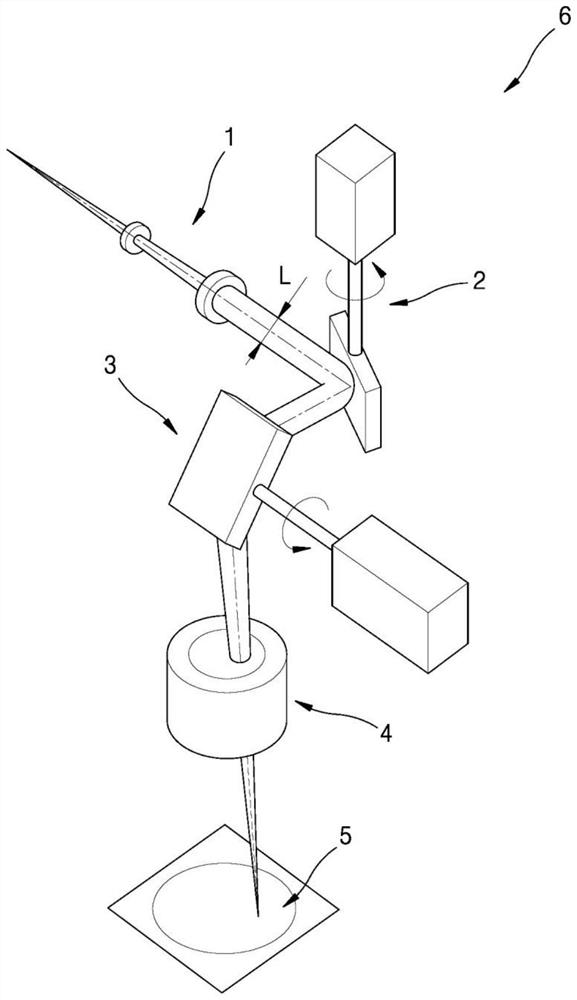
[0003] In order to change the direction of the laser beam, this conventional laser drilling device needs to drive the first and second scanner modules 2 and 3 at the same time, so there is a limitation in realizing high-speed drilling.
In addition, when the area to be irradiated with the laser beam relative to the workpiece is relatively large, it is necessary to irradiate the laser beam while moving the workpiece arranged under the f-field focusing lens module 4 by using a platform, and thus an additional device for moving the workpiece is required. The platform has the disadvantages of increased cost and complicated installation

Method used


Image

  • Laser drilling device
  • Laser drilling device
  • Laser drilling device

Examples


Embodiment Construction

[0032] Preferred embodiments of the present invention will be described in detail below with reference to the accompanying drawings.

[0033] figure 2 is a conceptual diagram of a laser drilling device according to an embodiment of the present invention, image 3 is showing figure 2 A diagram of the state in which the optical axis moving part is rotated 180 degrees, Figure 4 is shown from figure 2 Punch to image 3 The top view of the state, Figure 5 yes figure 2 A side view of the state in which the optical axis moving part is rotated and punched. Figure 6 is showing figure 2 The diagram of the state where the focal length of the laser beam is changed to f2 in Figure 7 yes Figure 6 A side view of the state in which the optical axis moving part is rotated and punched, Figure 8 is showing Figure 6 In the state where the focal length of the laser beam is changed to f3, Figure 9 is showing Figure 8 A side view of the state in which the optical axis movi...


PUM


Abstract

The invention relates to a laser drilling device. This laser drilling device is characterized by comprising: a zoom module that varies the focal length of a laser beam; an optical axis moving unit that moves the laser beam by a predetermined distance with respect to a reference optical axis and emits the laser beam when the optical axis of the laser beam passing through the zoom module is incident is referred to as the reference optical axis; a first drive unit that rotates the optical axis moving unit; a first focusing lens that focuses the laser beam that has passed through the optical axis moving unit; wherein the optical axis moving part is rotated by means of the driving part, the focal length of the laser beam is gradually increased by means of the zoom module, and the workpiece surface is punched at the same time.

Description

technical field [0001] The present invention relates to a laser drilling device, and more particularly to a laser drilling device capable of rapidly performing hole processing by moving the optical axis of an incident laser beam to change the irradiation position on the surface of a workpiece, and rotating an optical axis moving part. Background technique [0002] figure 1 An example of a laser drilling device according to the prior art is shown. The laser drilling device according to the prior art includes a focus variable module 1 that makes the focus of the laser beam variable, a first scanner module 2 and a second scanner module 3 that make the irradiation position of the laser beam variable, and a laser beam that focuses the laser beam. The optical flat-field focusing lens module (focus-theta lens) 4 constitutes. The laser beams passing through the respective devices are irradiated onto the irradiation surface 5 of a predetermined workpiece. [0003] In order to chan...

Claims


Application Information

Patent Timeline
IPC IPC(8): B23K26/382B23K26/06
CPCB23K26/382B23K26/0643B23K26/06B23K26/0648B23K26/04B23K26/082B23K26/0652
Inventor 崔完海
Owner INNOPHOTONICS CORP
Learn More