Manufacturing tool for camshaft bearing cap

A technology for bearing caps and camshafts, which is applied to manufacturing tools, supports, positioning devices, etc., can solve the problems of high pass rate, slow efficiency, low pass rate, etc., to reduce the replacement cycle and efficiency, simplify the processing process, and the technological process. simple effect

Pending Publication Date: 2022-04-29
芜湖格力精密制造有限公司 +1
View PDF0 Cites 0 Cited by
  • Summary
  • Abstract
  • Description
  • Claims
  • Application Information

AI Technical Summary

Problems solved by technology

[0003] However, in the existing manufacturing process, because the structure of the camshaft bearing cap is complex, the production efficiency is low, and the tolerance requirements for the camshaft perimeter cap are relatively high during production, which results in the simultaneous processing of a batch of products with different specifications The pass rate is low during the inspection, so it is difficult to realize the processing technology and tooling with simple process flow, high pass rate and low cost in the production process of quick change and sequence change of camshaft bearing caps
At the same time, the status quo in the industry is to change the type of camshaft bearing cap and change the sequence of camshaft bearing cap through the overall replacement of tooling. The disadvantage of this is that the replacement cycle is long and the efficiency is slow.

Method used


Image

  • Manufacturing tool for camshaft bearing cap
  • Manufacturing tool for camshaft bearing cap
  • Manufacturing tool for camshaft bearing cap

Examples


Embodiment 1

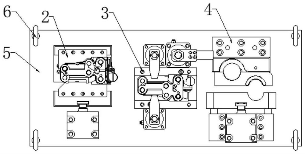
[0026] This example provides Figure 1-5 A preparation tool for a camshaft bearing cover is shown, wherein the preparation tool includes several positioning mechanisms; the positioning mechanism has a pressing assembly for pressing and a positioning assembly for positioning, and the pressing assembly and positioning assembly are arranged on the bottom plate 5 on.

[0027] The positioning mechanism includes a first positioning mechanism 1 , a second positioning mechanism 2 , a third positioning mechanism 3 and a fourth positioning mechanism 4 .

[0028] Each positioning mechanism is further described, wherein the first positioning mechanism 1 includes a first pressing assembly 11 and a first positioning assembly 12; the first pressing assembly 11 is connected with the first positioning assembly 12, and the first pressing assembly 11 and the first positioning component 12 are respectively arranged on the first mounting plate 13 . The second positioning mechanism 2 includes a s...

Embodiment 2

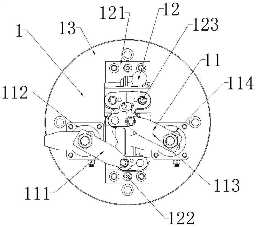
[0032] This example provides Figure 1-2 A preparation tool for a camshaft bearing cap is shown, wherein the preparation tool includes a first positioning mechanism 1, and the first positioning mechanism 1 includes a first pressing assembly 11 and a first positioning assembly 12; the first pressing assembly 11 and The first positioning component 12 is connected, and the first pressing component 11 and the first positioning component 12 are respectively arranged on the first mounting plate 13 .

[0033] The first pressing assembly 11 and the first positioning assembly 12 are described in detail below, as attached figure 1 As shown, the first pressing assembly 11 includes a first left pressing arm 111, a first left oil cylinder 112, a first right pressing arm 113 and a first right oil cylinder 114; a first left pressing arm 111 is arranged on the first left oil cylinder 112, The first right oil cylinder 114 is arranged on the first right oil cylinder 114, and the first left pre...

Embodiment 3

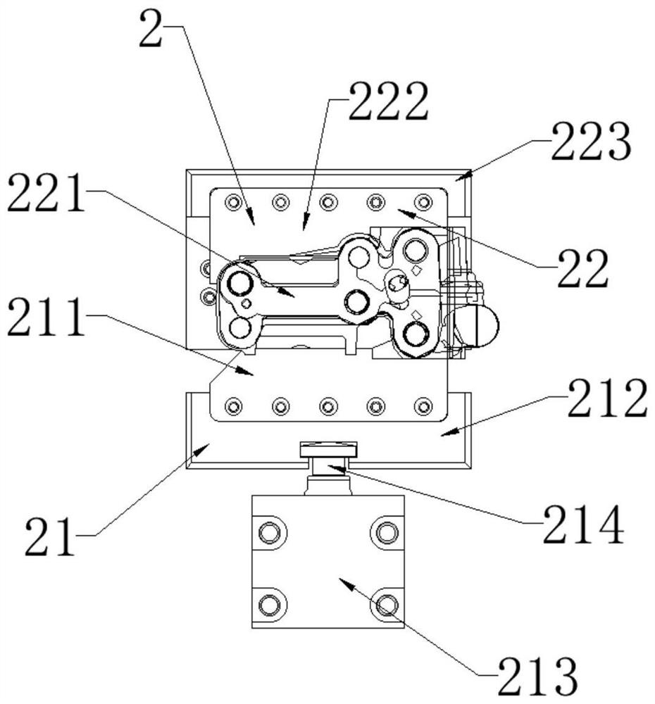
[0036] This example provides Figure 2-3 A preparation tooling for a camshaft bearing cap is shown, wherein the preparation tooling also includes a second positioning mechanism 2, and the second positioning mechanism 2 includes a second pressing assembly 21 and a second positioning assembly 22; the second pressing assembly 21 Connect with the second positioning component 22.

[0037] The second pressing assembly 21 and the second positioning assembly 22 are described in detail below, as attached image 3 As shown, the second pressing assembly 21 includes a second pressing plate 211, a second pressing slider 212, a second oil cylinder 213 and a second oil cylinder ejector rod 214; a second oil cylinder spacer is arranged under the second oil cylinder 213, and the second oil cylinder 213 is connected with the second cylinder jack 214, the second cylinder jack 214 is connected with the second compression slider 212, and the second compression slider 212 is connected with the secon...


PUM


Abstract

The invention provides a camshaft bearing cap manufacturing tool which comprises a plurality of positioning mechanisms. The positioning mechanism is provided with a pressing assembly used for pressing and a positioning assembly used for positioning, and the pressing assembly and the positioning assembly are arranged on the bottom plate. The machining process of the camshaft bearing cover can be effectively simplified, rapid switching of the camshaft bearing cover in the machining process can be achieved, the production efficiency, the machining tolerance accuracy rate and the qualified rate during detection are improved, and in the rapid type changing and sequence changing production process of the camshaft bearing cover, the production efficiency is improved. The machining technology and the tool are simple in technological process, high in percent of pass and low in cost. And meanwhile, the replacement period and efficiency of tool machining are reduced.

Description

technical field [0001] The invention relates to the technical field of engines, in particular to a preparation tool for a camshaft bearing cap. Background technique [0002] The camshaft bearing cap is a component mounted on the cylinder head of the engine. Due to the various models and types of engines, the models and styles of camshaft bearing caps are also complex and varied. In addition, the dimensions of parts of different camshaft bearing caps are also different. [0003] However, in the existing manufacturing process, because the structure of the camshaft bearing cap is complex, the production efficiency is low, and the tolerance requirements for the camshaft perimeter cap are relatively high during production, which results in the simultaneous processing of a batch of products with different specifications The pass rate is low during testing, so it is difficult to realize the processing technology and tooling with simple process flow, high pass rate and low cost in ...

Claims


Application Information

Patent Timeline
Patent Type & Authority Applications(China)
IPC IPC(8): B23Q3/08
CPCB23Q3/082
Inventor 林志华张强吴边苏江涛乔兴茂
Owner 芜湖格力精密制造有限公司
Why Eureka
Try Eureka