
Intelligent servo feeding and positioning mechanism for piston rod machining

A feeding positioning mechanism and servo feeding technology, which is applied in metal processing and other directions, can solve the problems affecting the orderly progress of piston rod processing operations, low product turnover rate, and large process inventory, so as to improve product turnover rate and reduce process Inventory, the effect of improving accuracy and efficiency

Active Publication Date: 2022-04-29
QINGDAO ZHANGSHI MACHINERY
View PDF16 Cites 0 Cited by
  • Summary
  • Abstract
  • Description
  • Claims
  • Application Information

AI Technical Summary

Problems solved by technology

[0004] One: The two processing processes are processed separately, resulting in large process inventory and low product turnover rate;
[0005] Two: When the equipment of the two processes is changing the product type, it is necessary to manually position and adjust the position of the piston rod repeatedly and many times, which leads to low processing efficiency;
[0006] Three: When putting the blanks to be processed into the processing equipment, due to the lack of a single feeding device, multiple blanks are easy to accumulate at the feeding port of the processing equipment during loading, which affects the Orderly conduct of piston rod machining operations

Method used


Image

  • Intelligent servo feeding and positioning mechanism for piston rod machining
  • Intelligent servo feeding and positioning mechanism for piston rod machining
  • Intelligent servo feeding and positioning mechanism for piston rod machining

Examples


Embodiment Construction

[0033] In order to make the purpose, technical solutions and advantages of the embodiments of the present invention more clear, the technical solutions in the embodiments of the present invention will be clearly and completely described below in conjunction with the accompanying drawings in the embodiments of the present invention. Obviously, the described embodiments It is a part of embodiments of the present invention, but not all embodiments. Based on the embodiments of the present invention, all other embodiments obtained by persons of ordinary skill in the art without making creative efforts belong to the protection scope of the present invention.

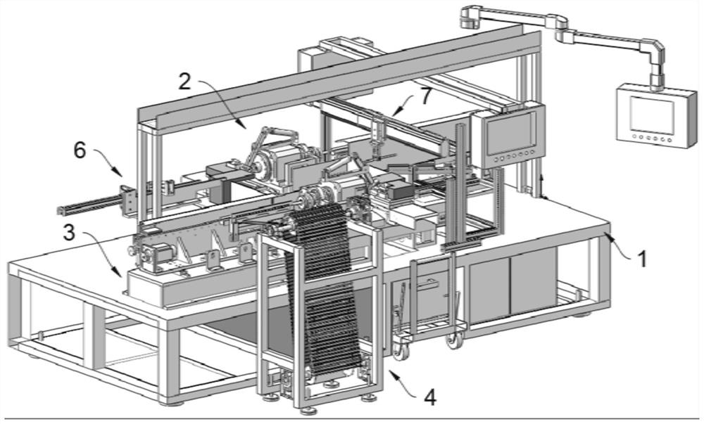
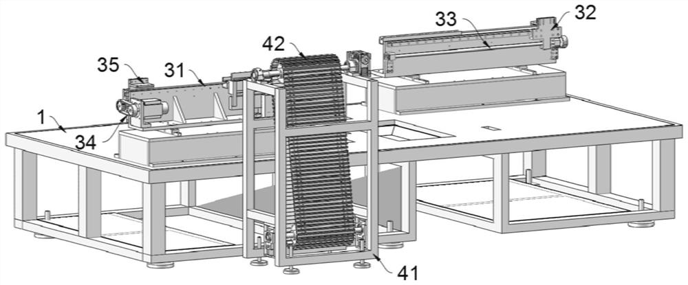
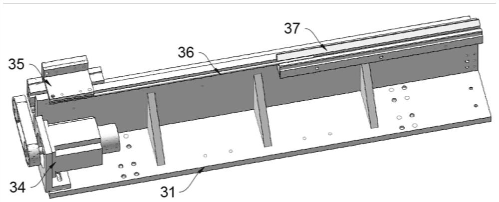
[0034] The present invention provides such Figure 1-8 The shown piston rod processing intelligent servo feeding positioning mechanism includes an equipment base 1, and the top of the equipment base 1 near the front and rear sides is equipped with a permanent magnet motor numerical control processing machine 2, and two permane...


PUM


Abstract

The invention belongs to the technical field of piston rod machining equipment, and particularly relates to an intelligent servo feeding and positioning mechanism for piston rod machining. The mechanism comprises an equipment base, permanent magnet motor numerical control machining machines are installed at the positions, close to the front side and the rear side, of the top of the equipment base correspondingly, the machining ends of the two permanent magnet motor numerical control machining machines are opposite, and feeding positioning mechanisms are arranged at the feeding ends of the two permanent magnet motor numerical control machining machines correspondingly; a feeding mechanism is arranged on the front side of the feeding and positioning mechanism located on the front side, and a single-support discharging mechanism is arranged between the feeding mechanism and the feeding and positioning mechanism located on the front side. By arranging the two permanent magnet motor numerical control machining machines and the feeding mechanism, the feeding positioning mechanism, the single discharging mechanism, the material taking machine and the material moving machine which are used in cooperation with the two permanent magnet motor numerical control machining machines, equipment of two working procedures of piston rod machining is optimized and integrated, and therefore working procedure inventory is reduced; and the product turnover rate is improved.

Description

technical field [0001] The invention belongs to the technical field of piston rod processing equipment, in particular to an intelligent servo feeding positioning mechanism for piston rod processing. Background technique [0002] The piston rod is a connecting part that supports the work of the piston. Most of them are used in oil cylinders, cylinder motion actuators and gas springs. It is a moving part with frequent movements and high technical requirements. The quality of its processing directly affects the life and reliability. [0003] Among them, the processing process of piston rods for gas springs is mainly divided into two processes, namely threaded end processing and riveting end processing. However, the current method of processing piston rods for gas springs mainly has the following shortcomings: [0004] One: The two processing processes are processed separately, resulting in large process inventory and low product turnover rate; [0005] Two: When the equipment...

Claims


Application Information

Patent Timeline
Patent Type & Authority Applications(China)
IPC IPC(8): B23Q7/00
CPCB23Q7/00
Inventor 张焕钰张茂银李在山
Owner QINGDAO ZHANGSHI MACHINERY
Learn More