Special grinding machine for removing welding spots of iron handicrafts

A handicraft and grinding machine technology, which is applied in the direction of abrasive jet machine tools, used abrasive processing devices, abrasives, etc., can solve the problem of labor-intensive manual rotation, and achieve the effect of reducing repeated pushing operations

Active Publication Date: 2022-04-29
厦门卓艺工贸有限公司
View PDF15 Cites 0 Cited by
  • Summary
  • Abstract
  • Description
  • Claims
  • Application Information

AI Technical Summary

Problems solved by technology

[0005] Aiming at the deficiencies of the prior art, the present invention provides a special grinding machine for removing solder joints of iron handicrafts, which can automatically rotate iron handicrafts and save manpower, so as to overcome the disadvantage that the existing grinding devices require manpower to rotate manually

Method used


Image

  • Special grinding machine for removing welding spots of iron handicrafts
  • Special grinding machine for removing welding spots of iron handicrafts
  • Special grinding machine for removing welding spots of iron handicrafts

Examples


Embodiment 1

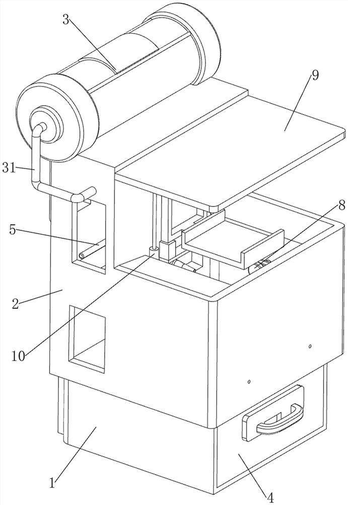
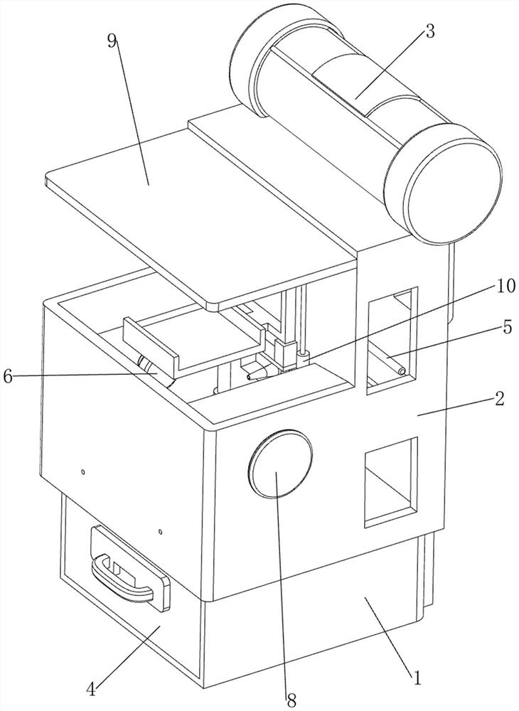
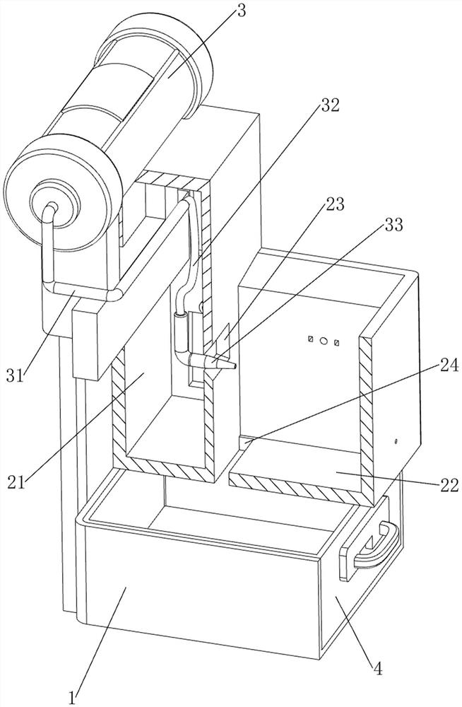
[0031] A special grinding machine for removing solder joints of iron handicrafts, now for reference Figure 1-6 , including a base 1, an installation box 2, a sand blaster 3, a conduit 31, a hose 32, a nozzle 33, a collection box 4, a sandblasting mechanism 5 and a rotating mechanism 6, the upper side of the base 1 is provided with an installation box 2, and the installation box 2. It includes an outer box 21 and an inner box 22. An outer box 21 is provided on the upper left side of the base 1. An inner box 22 is connected between the right side of the outer box 21 and the base 1. A sandblasting groove 23 is opened on the lower side of the right side of the outer box 21. , the left side of the lower part of the inner box 22 has a sand outlet 24, the upper left side of the outer box 21 is provided with a sand blaster 3, the top of the sand blaster 3 is provided with a cover, and the base 1 is slidingly provided with a collection box 4, the collection box 4 For collecting sand, ...

Embodiment 2

[0036] On the basis of embodiment 1, now refer to Figure 7 , also includes a reciprocating mechanism 7, the reciprocating mechanism 7 includes a first rotating shaft 71, a spur gear set 72, a second rotating shaft 73, a transmission belt 74, a space cam 75 and a guide sleeve 76, and the right side of the inner box 22 is rotated. There is a first rotating shaft 71, the first rotating shaft 71 is rotationally connected with the support frame 61, a spur gear set 72 is connected between the first rotating shaft 71 and the transmission shaft 63, the spur gear set 72 includes two spur gears, the first rotating shaft 71 Spur gears are arranged on the transmission shaft 63, and the two spur gears are meshed. A second rotating shaft 73 is provided on the lower side of the outer box 21 to rotate to the left. The second rotating shaft 73 is provided with a space cam 75. The second rotating shaft Between 73 and the first rotating shaft 71, a transmission belt 74 is wound around the trans...


PUM


Abstract

The invention relates to a welding spot grinding machine, in particular to a special grinding machine for removing welding spots of iron crafts. According to the special grinding machine for removing the welding spots of the iron handicrafts, the iron handicrafts can be automatically rotated, and manpower is saved. A special grinding machine for removing welding spots of iron crafts comprises a base, a mounting box, a sand blower and the like. A mounting box is arranged on the upper side of the base and comprises an outer box and an inner box, the outer box is arranged on the left side of the upper portion of the base, the inner box is connected between the right side of the outer box and the base, a sand blasting groove is formed in the lower side of the right portion of the outer box, a sand outlet groove is formed in the left side of the lower portion of the inner box, and a sand blaster is arranged on the left side of the upper portion of the outer box. According to the automatic rotating device, the iron artware is placed on the first magnet, the first magnet magnetically attracts the iron artware, then people start the driving motor, an output shaft of the driving motor rotates to drive the transmission shaft to rotate, the first magnet and the iron artware rotate, and therefore the automatic rotating effect is achieved; and the sand can polish all welding spots on the iron handicraft.

Description

technical field [0001] The invention relates to a welding spot grinding machine, in particular to a special grinding machine for removing welding spots of iron handicrafts. Background technique [0002] After the welding process of iron handicrafts is completed, solder joints will be formed on the surface. In order to make the appearance of iron handicrafts more beautiful, people will polish the solder joints. The existing grinding devices are prone to dust during grinding, and the dust generated during grinding It is easy to cause harm to the human body after being inhaled by people, so a grinding device needs to be designed. [0003] Patent application: CN210968187U, publication date 20200710, discloses a welding spot grinding device for well cover production, by placing the welding spot position on the well cover on the well cover so that the welding spot is located under the grinding disc, and then placing two magnet frames on the The periphery of the well cover, and tu...

Claims


Application Information

Patent Timeline
Patent Type & Authority Applications(China)
IPC IPC(8): B24C1/08B24C3/04B24C9/00
CPCB24C1/083B24C3/04B24C9/00B24C9/003Y02P70/10
Inventor 胡振雄梁晓霞李绿娟
Owner 厦门卓艺工贸有限公司
Why Eureka
Try Eureka