Press-fit device for building material plywood manufacturing

A technology for pressing devices and building materials, which is applied in plywood presses, veneer presses, manufacturing tools, etc., can solve the problems of poor bonding, uneven gluing, poor bonding effect, etc., to improve work efficiency. Efficient and effective

Active Publication Date: 2022-07-22
临沂长青树木业有限公司
View PDF10 Cites 0 Cited by
  • Summary
  • Abstract
  • Description
  • Claims
  • Application Information

AI Technical Summary

Problems solved by technology

A plywood pressing device according to the present invention touches and presses the upper surface of the plywood when the plywood is driven downward by the telescopic rod, the operation process is simple, and the work efficiency is improved. There are springs on both sides. When the pressing board moves down, the spring is in a compressed state, which can play a buffer role and prevent the plywood from being broken due to excessive pressure when the pressing board is quickly pressed. Pressing, but the device does not flatten the sheet during the bonding process, so it is easy to cause uneven gluing, resulting in poor bonding effect
[0004] We have designed an automatic rolling and flattening construction material plywood manufacturing pressing device to overcome the existing pressing device that does not flatten the veneer before bonding, resulting in poor bonding

Method used


Image

  • Press-fit device for building material plywood manufacturing
  • Press-fit device for building material plywood manufacturing
  • Press-fit device for building material plywood manufacturing

Examples


Embodiment 1

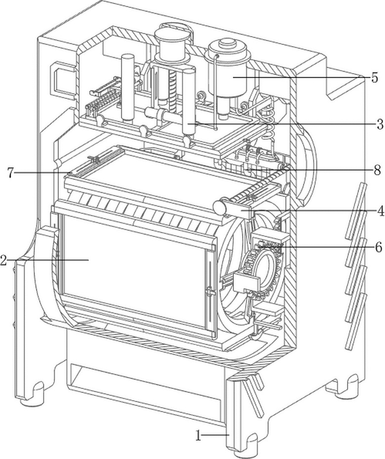
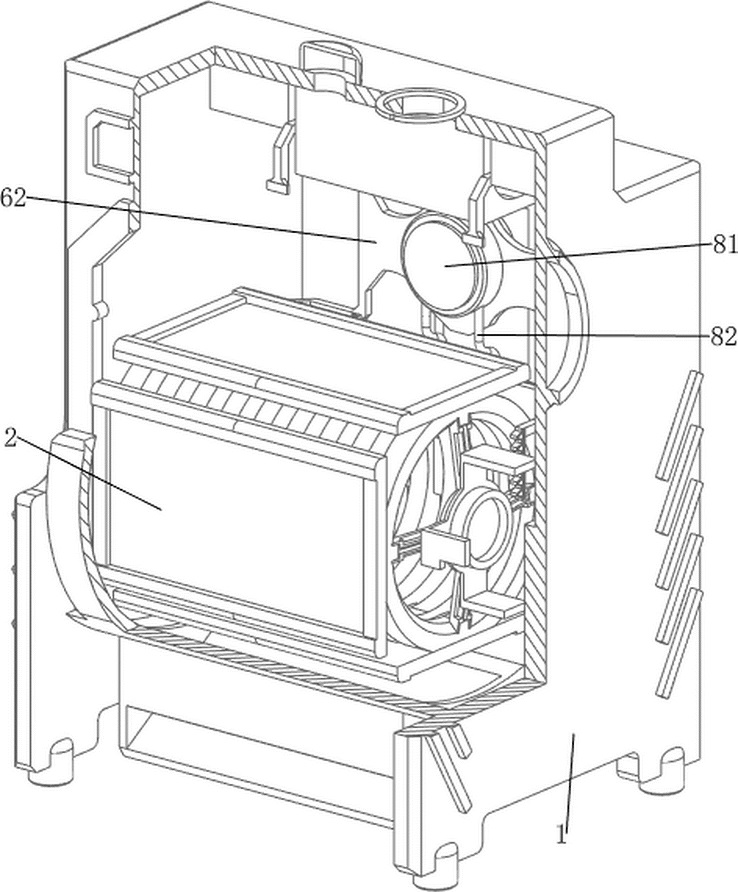
[0084] A construction material plywood manufacturing and pressing device, now refer to Figure 1-Figure 2 , including a mounting shell 1, a placing turret 2, a pressing mechanism 3 and a rolling mechanism 4, the mounting shell 1 is provided with a pressing mechanism 3, the inner and lower side of the mounting shell 1 is rotatably provided with a placing turret 2, and the mounting shell 1 is equipped with a rolling mechanism 4.

[0085] Reference now figure 2 , image 3 , Image 6 , Figure 8 , Figure 9 , Figure 10 , Figure 12 , Figure 13 and Figure 14 , the pressing mechanism 3 includes a first telescopic rod 31, a first servo motor 32, a first screw rod 33, a support frame 34, a pressing plate 35 and a first connecting frame 36, and the front and rear sides of the inner upper part of the installation casing 1 are provided with There are two first telescopic rods 31 , there are four first telescopic rods 31 , a pressing plate 35 is connected between the lower si...

Embodiment 2

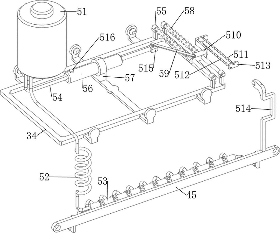
[0089] On the basis of Example 1, now refer to figure 2 , Image 6 , Figure 7 and Figure 8 , and also includes a glue spraying mechanism 5. The glue spraying mechanism 5 includes a liquid storage cylinder 51, a guide tube 52, a glue spray frame 53, a first air guide tube 54, a guide frame 55, an extrusion cylinder 56, a fixed frame 57, a first A spring 58, a first swing rod 59, a push frame 510, a first sliding rod 511, a second spring 512, a first top block 513, a top frame 514, a piston rod 515 and a one-way valve 517 are installed on the upper right side of the housing 1 A liquid storage cylinder 51 is provided. The liquid storage cylinder 51 is used for containing urea-formaldehyde glue. The liquid storage cylinder 51 is provided with a threaded cylinder cover. The lower side of the liquid storage cylinder 51 is provided with a guide tube 52. 53, the glue spraying frame 53 is connected with the guide pipe 52, the upper side of the front part of the liquid storage cyl...


PUM


Abstract

The invention relates to a plywood pressing device, in particular to a building material plywood manufacturing and pressing device. The invention provides a building material plywood manufacturing and pressing device capable of automatically rolling flat. The invention discloses a pressing device for building material plywood manufacturing. The pressing device comprises a mounting shell, a placement rotating frame, a pressing mechanism and a rolling and flattening mechanism. A placement rotating frame is rotationally arranged on the lower side in the mounting shell, a pressing mechanism is arranged in the mounting shell, and a rolling mechanism is arranged in the mounting shell. A second servo motor is started by people, an output shaft of the second servo motor rotates to drive a second lead screw to rotate, a rolling wheel moves forwards, and when the rolling wheel moves forwards to make contact with a thin plate, the rolling wheel rolls the thin plate to be flat, so that the automatic rolling effect is achieved, and the bonding effect is better.

Description

technical field [0001] The invention relates to a plywood pressing device, in particular to a plywood manufacturing pressing device for building materials. Background technique [0002] Plywood is a commonly used material in furniture. Before use, people will use urea-formaldehyde glue to bond multiple sheets into plywood for use. After the bonding is completed, people will press the plywood to make the bonding effect better. Therefore, it is necessary to Design a plywood pressing device. [0003] Patent application: CN213563168U, the publication date is 20210629, which discloses a plywood pressing device. By including a support table, the upper end of the support table is provided with a chute, and the groove wall of the chute is provided with a sliding limit device. A plywood is movably connected to the middle of the upper end of the support table, a U-shaped fixing frame is fixedly installed in the middle of the upper end of the support table, and a telescopic pressing d...

Claims


Application Information

Patent Timeline
Patent Type & Authority Applications(China)
IPC IPC(8): B27D1/08B27D3/00
CPCB27D1/083B27D3/00
Inventor 杨晓春
Owner 临沂长青树木业有限公司
Why Eureka
Try Eureka