Slag deposition and mud deposition prevention structure of normal-pressure tool changer

A tool changing device and slag accumulation technology, which is applied in mining equipment, mining equipment, tunnels, etc., can solve the problems of limited cleaning effect of water flushing, and achieve the effects of reducing the risk of tool changing, increasing construction efficiency, and reasonable structural design

Pending Publication Date: 2022-04-29
中铁工程装备集团隧道设备制造有限公司 +1
View PDF1 Cites 0 Cited by
  • Summary
  • Abstract
  • Description
  • Claims
  • Application Information

AI Technical Summary

Problems solved by technology

[0007] In order to solve the problem of limited cleaning effect of existing water washing, the present invention provides an anti-slag and mud accumulation structure of the normal pressure tool changing device. On the basis of optimizing water washing, a slag-discharging and slag-guiding structure is proposed to effectively ensure the stability of the hob run

Method used


Image

  • Slag deposition and mud deposition prevention structure of normal-pressure tool changer
  • Slag deposition and mud deposition prevention structure of normal-pressure tool changer
  • Slag deposition and mud deposition prevention structure of normal-pressure tool changer

Examples


Embodiment Construction

[0032] The specific embodiment of the present invention is described in detail below in conjunction with accompanying drawing:

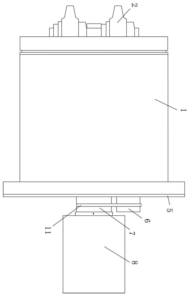
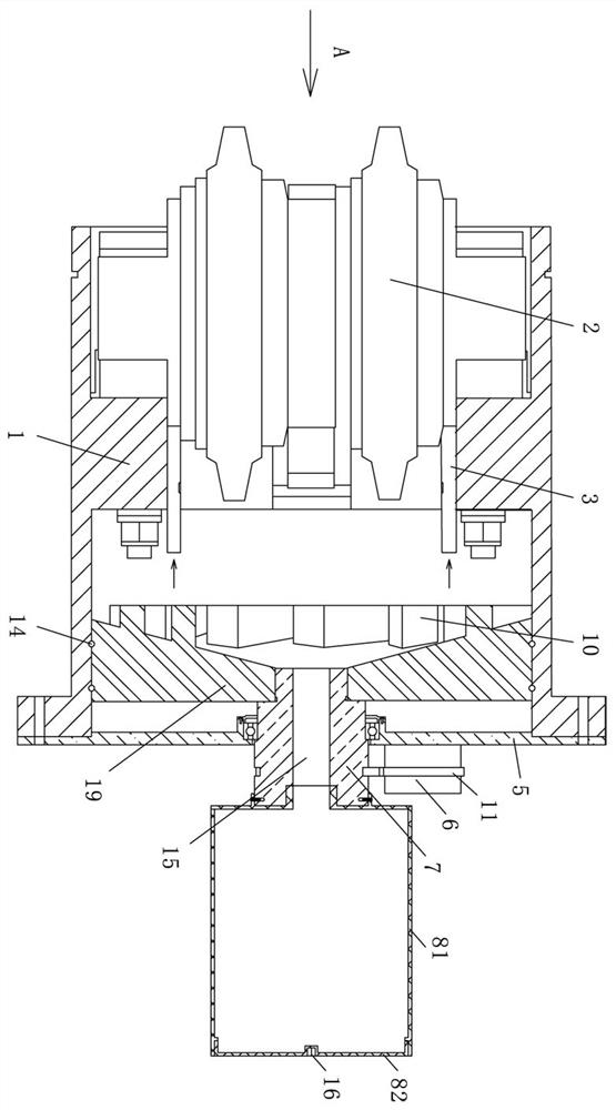
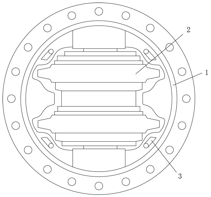
[0033] Such as Figure 1~Figure 7 As shown, a normal pressure tool changing device anti-slag and mud accumulation structure includes a knife barrel 1 and a hob 2 arranged in the knife barrel 1. The knife barrel 1 is hollow and cylindrical with two ends open, and the knife barrel 1. The hob 2 is arranged on the front end, and the hob 2 protrudes from the knife barrel 1.

[0034] In order to realize the flushing of the hob 2, four water spray pipes 3 with fan-shaped water spray holes 4 are provided on the upper circumference of the knife barrel 1 on the side of the hob 2, and the section of the water spray pipe 3 is " " " shape, and is positioned at knife barrel 1 front end.

[0035] Specifically, the water spray pipe 3 includes an axial section 31 and a radial section 32, and the axial section 31 and the radial section 32 are connected in a """ shap...


PUM


Abstract

The invention relates to a slag deposition and mud deposition prevention structure of a normal-pressure cutter changing device, which comprises a cutter barrel and a hob arranged in the cutter barrel, a plurality of water spray pipes with fan-shaped water spray holes are uniformly arranged on the cutter barrel on the peripheral side of the hob in the circumferential direction, and the water spray pipes are positioned at the front end of the cutter barrel; a residue guiding assembly is arranged at the rear end of the cutter barrel and comprises a mounting disc detachably connected to the cutter barrel, a driving motor arranged on the mounting disc, a hollow residue guiding column rotationally arranged in the middle of the mounting disc, a residue collecting disc and a residue storage barrel; the driving motor and the slag guide column are in belt transmission, one end of the slag guide column extends into the cutter barrel and is meshed with the middle of the slag collecting disc, one side of the slag collecting disc is a concave conical surface, and a plurality of slag collecting strips are uniformly arranged on the conical surface in the circumferential direction; the other end of the slag guide column extends out of the cutter barrel and is detachably connected with a slag storage barrel, and the slag collecting disc, the slag guide column and the slag storage barrel are sequentially communicated. Muck and the like are prevented from entering the cutter barrel through the high-water-pressure'water wall ', the phenomenon that the cutter barrel exhausts slag can be avoided, and eccentric wear of the hob can be avoided.

Description

technical field [0001] The invention relates to the technical field of shield hobs, in particular to a slag and mud accumulation prevention structure for an atmospheric pressure tool changing device. Background technique [0002] With the continuous development of my country's economic construction, urban rail transit and subways have developed rapidly. Because shield machines are green, efficient, and have the characteristics of little disturbance to the ground, shield machines are often used for tunnel development in urban subway construction. [0003] my country's geological conditions are diverse and very complicated. When encountering mudstone, clay, sandy clay, sandy mudstone and other highly cohesive strata, the hob and the excavation surface will be ground for a long time, and the clay will always be ground. , soil, rock slag, etc. are brought into the knife barrel, causing the knife barrel to be full of slag. [0004] The slag in the knife barrel has poor fluidity, ...

Claims


Application Information

Patent Timeline
Patent Type & Authority Applications(China)
IPC IPC(8): E21D9/08E21D9/12E21F17/00
CPCE21D9/08E21D9/12E21F17/00
Inventor 李建斌尚勇王锴孙堂超张世伟张天增姜海峰
Owner 中铁工程装备集团隧道设备制造有限公司
Why Eureka
Try Eureka