
Air compressor joint control method and system and storage medium

An air compressor and joint control technology, applied in pump control, mechanical equipment, machine/engine, etc., can solve the problems of increasing difficulty, many lines of joint control equipment, and large amount of data, so as to reduce the pressure of data processing and improve real-time Response speed, the effect of reducing the number of lines

Pending Publication Date: 2022-04-29
ZHONGSHAN CITY AINENG MACHINERY
View PDF0 Cites 0 Cited by
  • Summary
  • Abstract
  • Description
  • Claims
  • Application Information

AI Technical Summary

Problems solved by technology

This situation not only brings difficulties to the unified management of the air compressor network, but also brings great challenges to the joint control of multiple air compressor networks
[0003] At present, the common solution in the market is to configure a set of joint control equipment to control all air compressors in a unified network, but there will be many problems in this way: 1. Different air compressors have inconsistent network spaces, long distances, and signal transmission. Real-time performance is affected
2. Different air compressor networks often have a large number of air compressors and a large amount of transmitted data. The joint control equipment may not be able to withstand the huge amount of data processing and cause the system to stop unexpectedly
3. Due to the huge number of air compressors, there are too many local lines of the joint control equipment, which is not only prone to interference, but also greatly increases the difficulty of subsequent after-sales service

Method used


Image

  • Air compressor joint control method and system and storage medium
  • Air compressor joint control method and system and storage medium
  • Air compressor joint control method and system and storage medium

Examples


Embodiment 1

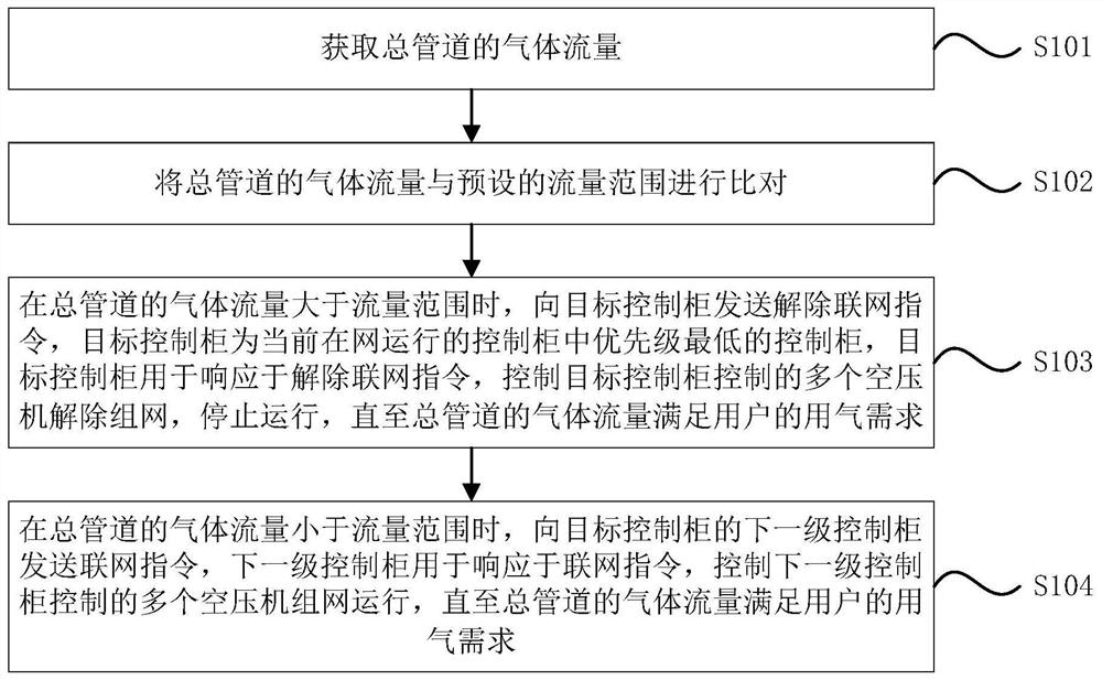
[0049] Figure 1AIt is a flow chart of an air compressor joint control method provided by Embodiment 1 of the present invention. This embodiment is applicable to the situation of multi-stage air compressor joint control. device, which can be implemented by software and / or hardware, and configured in the joint control cabinet provided by the embodiment of the present invention, such as Figure 1A As shown, the method specifically includes the following steps:

[0050] S101. Obtain the gas flow rate of the main pipeline.

[0051] Due to limited factory planning and local space, all air compressors cannot be placed in the same space, and often need to be placed separately in different places to form different air compressor networks, and then the compressed air produced by them Together, they will be aggregated to the manager, and will be uniformly supplied to the terminal.

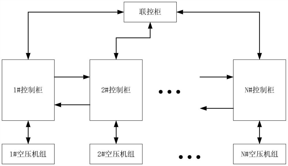
[0052] Figure 1B A schematic structural diagram of an air compressor joint control system provided for...

Embodiment 2

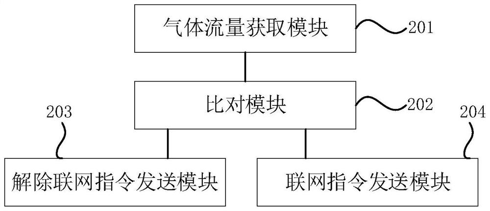
[0093] figure 2 A schematic structural diagram of an air compressor joint control device provided in Embodiment 2 of the present invention, as shown in figure 2 As shown, the device includes:

[0094] A gas flow acquisition module 201, configured to acquire the gas flow of the main pipeline;

[0095] A comparison module 202, which compares the gas flow of the total pipeline with a preset flow range;

[0096] The disconnection command sending module 203 is used to send a disconnection command to the target control cabinet when the gas flow rate of the main pipeline is greater than the flow range, and the target control cabinet has the lowest priority among the control cabinets currently running on the network control cabinet, the target control cabinet is used to respond to the de-network instruction, control the multiple air compressors controlled by the target control cabinet to de-network and stop running until the gas flow of the main pipeline meets the user’s requireme...

Embodiment 3

[0116] Embodiment 3 of the present invention provides an air compressor joint control system, the air compressor joint control system includes:

[0117] Multiple air compressors;

[0118] Multiple control cabinets, each of which controls multiple air compressors;

[0119]A joint control cabinet, the joint control cabinet is connected to the plurality of control cabinets.

[0120] The structure of the air compressor joint control system can be described in the foregoing embodiments and Figure 1B , the embodiment of the present invention will not be repeated here.

[0121] image 3 It is a schematic structural diagram of the joint control cabinet in the embodiment of the present invention, as image 3 As shown, the joint control cabinet includes:

[0122] Processor 301, memory 302, communication module 303, input device 304 and output device 305; the number of processors 301 can be one or more, image 3 Take a processor 301 as an example; the processor 301, the memory 302...


PUM


Abstract

The invention discloses an air compressor joint control method and system and a storage medium. The gas flow of the main pipeline is compared with a preset flow range, when the gas flow of the main pipeline is larger than the flow range, a networking releasing instruction is sent to a target control cabinet, the target control cabinet is the control cabinet with the lowest priority in the control cabinets currently operating in the network, and when the gas flow of the main pipeline is smaller than the flow range, the networking releasing instruction is sent to the target control cabinet. And sending a networking instruction to the next-level control cabinet of the target control cabinet. Networking control over the air compressor sets controlled by the control cabinets is achieved through cascading of the control cabinets, the control cabinets and the corresponding air compressor sets can be arranged in the same space, the distance between the control cabinets and the air compressors is reduced, the real-time response speed of the air compressors is increased, the data processing pressure of the joint control machine is relieved, and the reliability of the joint control machine is improved. Meanwhile, the number of lines between the joint control cabinet and the air compressor is reduced, interference between the lines is reduced, and subsequent after-sale difficulty is reduced.

Description

technical field [0001] Embodiments of the present invention relate to air compressor control technology, and in particular to an air compressor joint control method, system and storage medium. Background technique [0002] Air compressors (referred to as air compressors) are equipment used to compress gas to provide pipe network pressure, and are usually placed in a separate space in groups. Due to limited factory planning and local space, all air compressors cannot be placed in the same space, and often need to be placed separately in different places to form different air compressor networks, and then the compressed air produced by them Together, they will be aggregated to the main pipe network and supplied to the terminal in a unified manner. This situation not only brings difficulties to the unified management of the air compressor network, but also brings great challenges to the joint control of multiple air compressor networks. [0003] At present, the common solutio...

Claims


Application Information

Patent Timeline
Patent Type & Authority Applications(China)
IPC IPC(8): F04B49/06F04B49/02F04B49/00F04B41/06
CPCF04B49/065F04B49/02F04B49/007F04B41/06
Inventor 马国荣
Owner ZHONGSHAN CITY AINENG MACHINERY
Learn More