Method, device and system for identifying cavity capacity through vibration measurement

A vibration measurement and chamber technology, which is applied in the direction of measuring devices, measuring capacity, volume measuring instruments/methods, etc., can solve the problems of the chamber losing its transfer function, stalling, failure, etc.

Pending Publication Date: 2022-04-29
SHANGHAI POWER EQUIP RES INST
View PDF0 Cites 0 Cited by
  • Summary
  • Abstract
  • Description
  • Claims
  • Application Information

AI Technical Summary

Problems solved by technology

[0002] For the storage and transportation of fuel, ore, and raw materials for large-scale industrial equipment, tanks, tanks, and air chambers are required for transshipment and temporary storage. Because the fuel, ore, and raw materials are affected by humidity and particle size, it is easy to In the body of the cylinder, tank and other chambers, there is a cohesive accumulation of quality, resulting in poor circulation and blockage.
[0003] For equipment chambers such as raw coal bunkers in thermal power plants and air chambers in waste incineration power plants, they are easily affected by coal materials bonded to coal bunkers or waste slag bonded air chambers during the process of coal falling and grate furnace waste incineration. When the situation arises, when the contents of the chamber stick to the inner wall of the chamber, the chamber will experience poor circulation of the internal material, and finally cause the chambers such as cylinders and tanks to become clogged and lose their original transshipment function, even when these bonds are under the action of some external vibration or other factors, the internal stress of the bond will be reduced or disappeared and will form an instant collapse. This kind of instantaneous impact can easily lead to the failure of the tail equipment, failure and other stalling phenomena, thus causing more harm
[0004] In the past, some material level gauges installed in the internal chamber were used to continuously monitor the material level for this situation. However, for raw coal bunkers, waste incineration plant furnace exhaust chambers, etc., the influence of dust, high temperature and other harsh environments As a result, compact electronic components such as level gauges may be damaged, fail, or other situations that cannot guarantee the measurement effect, and ultimately the internal bonding failure of the chamber body caused by measurement failure cannot be avoided.

Method used


Image

  • Method, device and system for identifying cavity capacity through vibration measurement
  • Method, device and system for identifying cavity capacity through vibration measurement
  • Method, device and system for identifying cavity capacity through vibration measurement

Examples


Embodiment 1

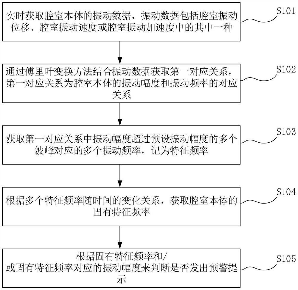
[0066] figure 1 It is a flow chart of the method for identifying chamber capacity through vibration measurement proposed by the embodiment of the first aspect of the present invention. Such as figure 1 As shown, the method for identifying chamber capacity through vibration measurement includes the following steps:

[0067] S101, acquiring vibration data of the chamber body in real time, the vibration data including one of chamber vibration displacement, chamber vibration velocity, or chamber vibration acceleration;

[0068] Wherein, the vibration data can be collected by a vibration sensor arranged on the chamber body. Vibration sensors are classified into one of displacement vibration sensors, velocity vibration sensors and acceleration vibration sensors.

[0069] If the vibration sensor is a displacement vibration sensor, the acquired vibration data of the chamber body is the vibration displacement data; if the vibration sensor is a velocity vibration sensor, the acquired...

Embodiment 2

[0106] Figure 5 It is a schematic block diagram of the device for identifying chamber capacity through vibration measurement proposed by the embodiment of the second aspect of the present invention. Such as Figure 5 As shown, the device 100 for identifying chamber capacity through vibration measurement includes:

[0107] A vibration data acquisition module 101, configured to acquire vibration data of the chamber body in real time, the vibration data including at least one of the vibration displacement of the chamber, the vibration velocity of the chamber, or the vibration acceleration of the chamber;

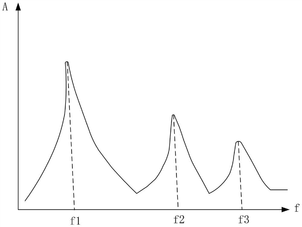
[0108] The first corresponding relationship acquisition module 102 is used to obtain the first corresponding relationship by combining the vibration data with the Fourier transform method, and the first corresponding relationship is the corresponding relationship between the vibration amplitude and the vibration frequency of the chamber body;

[0109] The characteristic freq...

Embodiment 3

[0130] Figure 6 It is a schematic structural diagram of a system for identifying chamber capacity through vibration measurement according to the embodiment of the third aspect of the present invention. Such as Figure 6 As shown, the system 200 for identifying chamber capacity through vibration measurement includes:

[0131] At least one vibration sensor 201 is fixed on the outer wall of the chamber body 203 through a fixed base 202;

[0132] Data acquisition card 204, one end is connected with vibration sensor 201, the other end is connected with processor 205, and another end is connected with power supply 206; The other end of vibration sensor 201 is connected with power supply 206;

[0133] The power supply 206 is used to supply power to the vibration sensor 201, the data acquisition card 204 is used to collect the vibration data of the chamber body 203 obtained by the vibration sensor 201, and the processor 205 is used to execute the method for identifying the chamber ...


PUM


Abstract

The invention discloses a method, device and system for identifying cavity capacity through vibration measurement, and the method comprises the following steps: obtaining the vibration data of a cavity body in real time, and obtaining a first corresponding relation through a Fourier transform method in combination with the vibration data, the first corresponding relation being the corresponding relation between the vibration amplitude and the vibration frequency of the cavity body; acquiring a plurality of vibration frequencies corresponding to a plurality of wave crests of which the vibration amplitudes exceed a preset vibration amplitude in the first corresponding relation, and recording the vibration frequencies as characteristic frequencies; according to the change relation of the multiple characteristic frequencies along with time, the inherent characteristic frequency of the cavity body is obtained; and according to the inherent characteristic frequency and / or the vibration amplitude corresponding to the inherent characteristic frequency, whether an early warning prompt is sent out is judged. On the basis that original structures of a barrel, a tank, an air chamber and the like in industrial equipment are not affected, whether the barrel, the tank and the air chamber are internally blocked or not is recognized, and therefore workers are warned in time when the barrel, the tank and the air chamber are internally blocked.

Description

technical field [0001] Embodiments of the present invention relate to the technical field of chamber body capacity identification, and in particular, to a method, device and system for identifying chamber capacity through vibration measurement. Background technique [0002] For the storage and transportation of fuel, ore, and raw materials for large-scale industrial equipment, tanks, tanks, and air chambers are required for transshipment and temporary storage. Because the fuel, ore, and raw materials are affected by humidity and particle size, it is easy to In the chamber body such as the cylinder body and the tank body, the quality is bonded and accumulated, resulting in poor circulation and blockage. [0003] For equipment chambers such as raw coal bunkers in thermal power plants and air chambers in waste incineration power plants, they are easily affected by coal materials bonded to coal bunkers or waste slag bonded air chambers during the process of coal falling and grat...

Claims


Application Information

Patent Timeline
Patent Type & Authority Applications(China)
IPC IPC(8): G01F17/00
CPCG01F17/00
Inventor 汪勇林润达陈荣泽叶晶邓志成陈家颖孙猛
Owner SHANGHAI POWER EQUIP RES INST
Why Eureka
Try Eureka