Intelligent industrial control system
An industrial control system and intelligent technology, applied in general control systems, control/regulation systems, program control, etc., can solve problems such as weak safety awareness, insufficient equipment safety detection methods, and difficulty in clearly displaying equipment usage, etc., to achieve security Internal stability, the effect of ensuring internal security
- Summary
- Abstract
- Description
- Claims
- Application Information
AI Technical Summary
Problems solved by technology
Method used
Image
Examples
Embodiment 1
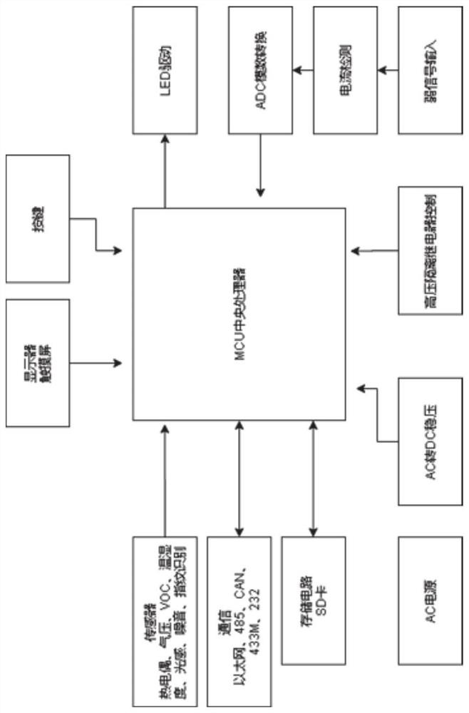
[0034] Example 1, such as figure 1 As shown, an intelligent industrial control system includes: a main control module, a power supply circuit, a display circuit, a sensor circuit, a peripheral circuit, an optocoupler isolation circuit, an analog-to-digital conversion circuit, a communication circuit, and a noise recognition circuit. The power supply circuit It includes a voltage stabilizing circuit and a current detection circuit, the display circuit can display the operation of industrial production equipment, the sensor circuit can detect various data indicators, the peripheral circuit includes a variety of interfaces, and the optocoupler isolation circuit can Excluding other signal interference, the analog-to-digital conversion circuit can perform signal conversion, the communication circuit can perform data communication in various ways, and the noise identification circuit can collect information and perform noise control.
Embodiment 2
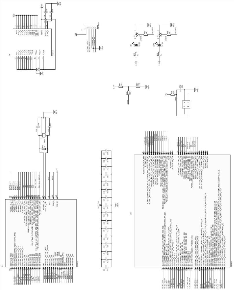
[0035] Example 2, such as figure 2 As shown, the main control module includes chips U5A, U5B, U5C, and interface J1, the pins 23 and 24 of the chip U5A are grounded through capacitors C34 and C35 respectively, and the crystal oscillator Y1 and resistor R46 are arranged on the tubes of the chip U5A. Between the pins 23 and 24, the first lead of the pin 138 of the chip U5A is connected to the power supply through the resistors R48 and R47, the second lead is grounded through the resistors R48 and R49, and the first lead of the pin 25 of the chip U5A is connected to the power supply through the resistors R48 and R47. The resistor R33 is connected to the power supply, the second lead is grounded through the capacitor C54, the pins 71 and 106 of the chip U5B are grounded through the capacitors C36 and C37 respectively, and the pins 105, 109, 96 and 97 of the chip U5C are connected to the interface J1 Pins 2, 3, 5, 6, pins 41, 42 are respectively connected to transistors Q2, Q3 thr...
Embodiment 3
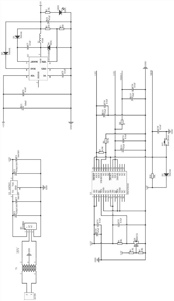
[0036] Example 3, such as image 3 , 4 As shown, the power supply voltage stabilization circuit includes chips U1-U3, U14, the chip U1 is a step-down circuit from 18V to 15V, the chip U2 is a step-down circuit from 15V to 5V, and the chip U3 is a step-down circuit from 15V to 3.3V and 1.8V step-down circuits, the chip U14 is a 5V to 1.8V step-down circuit, the model of the chip U1 is LM7815, the model of the chip U2 is CS51414EDR8, and the model of the chip U3 is TPS767D301 , the model of the chip U14 is RT9193-1.8, the current detection circuit includes chips U26, U27, interfaces P2, P4, CN2, CN3, CN6, CN7, the chips U26, U27 are 5V to 3.3V current detection circuit, the first leads of the pins 2 and 3 of the chip U26 are respectively connected to the pins 1 and 2 of the interface CN6, and the second and third leads are respectively grounded through resistors R151, R152 and capacitors C106 and C107. The first leads of the pins 6 and 7 of the chip U26 are respectively ground...
PUM
 Abstract
Description
Claims
Application Information
 - R&D
- Intellectual Property
- Life Sciences
- Materials
- Tech Scout
- Unparalleled Data Quality
- Higher Quality Content
- 60% Fewer Hallucinations
Browse by: Latest US Patents, China's latest patents, Technical Efficacy Thesaurus, Application Domain, Technology Topic, Popular Technical Reports.
© 2025 PatSnap. All rights reserved.Legal|Privacy policy|Modern Slavery Act Transparency Statement|Sitemap|About US| Contact US: help@patsnap.com


